


MODBUS TCP Settings

1. Set the Device MAC Address, Data Logger IP, Subnet Mask, Gateway and click on Save.
2. Slave ID: This is the MODBUS Slave ID. Maximum10 Slave info can be accessed.
3. Slave IP: Mention the IP Address of the Slave.
4.Socket: If the Slave IP address is same for multiple requests then the socket number will be the same.
If the IP address is different, then the socket number is different as shown above (Ex: For Slave ID 1 and
3 the slave IP is same (192.168.1.187) so the socket number should be the same (0)).
5.Slave Port No: Mention the Port No. (Default 502).
6.Start Address:6.This is the starting address of the slave from where data needs to be read.
7.Offset: Enter Offset of the Slave device.
8.Type: 8.Mention the register type. It could be Coil/Input Register/Holding Register.
9.Conversion:
Raw Hex: MODBUS 16 bits are extracted from slaves.
Integer: MODBUS 16 bits are extracted from slaves.
Double: MODBUS 16 bits are extracted from slaves.
Float-Big Endian: MODBUS floats are extracted from slaves in Big Endian format.
Float-Little Endian: MODBUS 16 bits are extracted from
slaves.
64 bit UINT: MODBUS 16 bits are extracted from slaves.
10.Length: Total length will be 100,you can use length of 1-100 of 16 bit data
11.Status: T11.If check box is enabled, the slave id will be ENABLED for polling, else slave id polling will be DISABLED.
12.Click on Savebutton to save the above configuration.
13.Click on Read to display the configuration that is already saved., to display the configuration that is already saved
14.Select the Polling Interval sec/min/hour
Note:
1. Device and Slave should be in same network
2. Max 100 registers can be scanned.
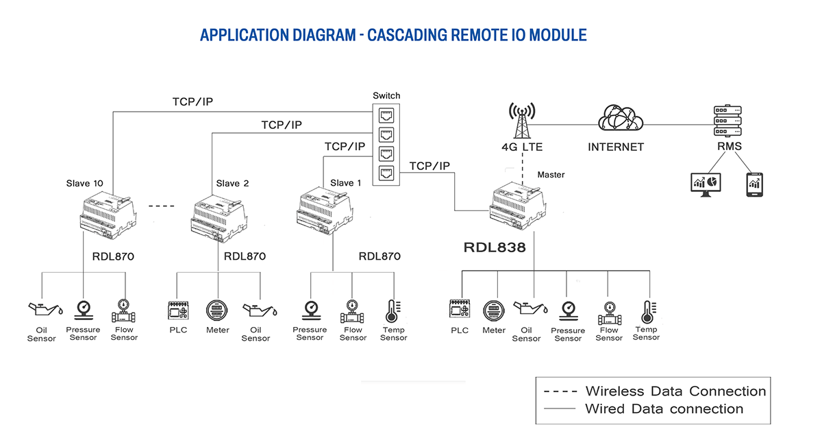
Application Wiring Diagram
