


Analog
Analog Channel Settings
The below given settings shows how to configure Loop current (4-20mA) and 0-10V Analog Channels.
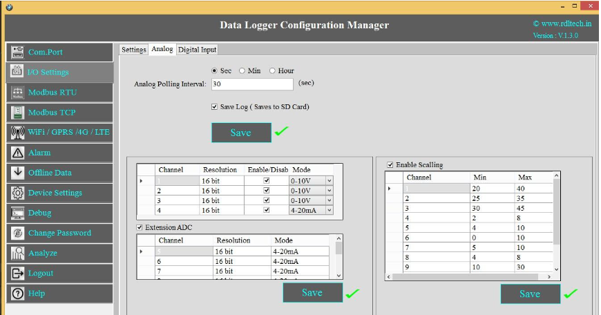
- Select the Polling Interval sec/min/hour
- Set the Polling Interval
- Save Log: Select the Check box
 to store the data to the SD Card.
 - Click on Save button will write these configuration settings in the memory.
- Select the Check box to Enable/Disable Analog channel
- Select 4-20mA / 0-10V from the dropdown.
- Extension ADC is an additional option under this the first four analog channels are for 4-20mA loop current and the next four for 0- 24V channel.
- Scaling: Click on the check boxto enable scaling. Scale the raw value of input to required output value.
- Click on Save button to save the above configuration.
- Click on Read, to display the configuration that is already saved.
Application Wiring Diagram
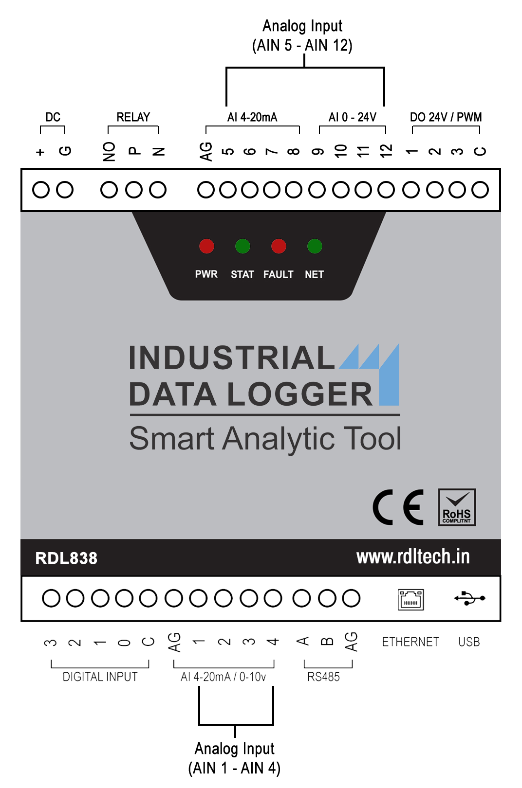
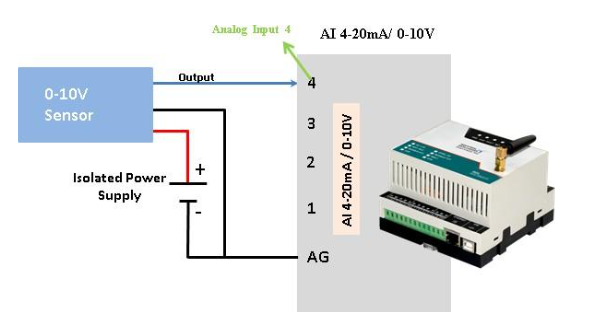
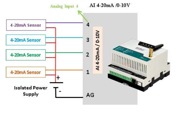
NOTE:Don’t connect Voltage source when Channel is set for Current Source Mode.
Video