Directions to install the ESP32 board on Arduino IDE
Installing the ESP32 Board in Arduino IDE
Before starting this installation method, make sure you have the latest version of the Arduino IDE 1.8.19 installed in your computer.
If you don’t, install it from https://www.arduino.cc/en/software , continue with this tutorial.
To install the ESP32 board in your Arduino IDE, follow these below instructions:
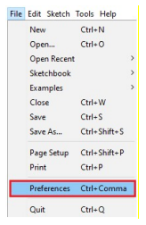
Step 1: In your Arduino IDE, go to File > Preferences
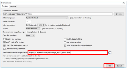
Step 2: Enter https://dl.espressif.com/dl/package_esp32_index.json into the “Additional Board Manager URLs” field as shown in the figure below. Then, click the “OK” button:
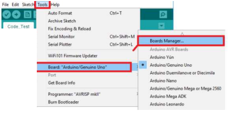
Step 3: Open the Boards Manager. Go to Tools > Board > Boards Manager…
Step 4: Search for ESP32 and press install button for the “ESP32 by Espressif Systems“:
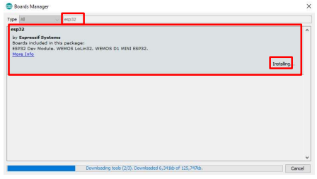
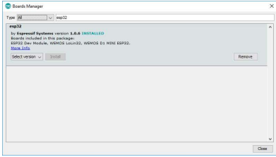
Step 5: ESP32 will be installed after a few seconds.
Video
Testing the Installation
Step 1: Plug the ESP32 Trainer Kit to your computer. With your Arduino IDE open, follow these steps:
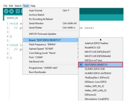
Step 2: Select your Board in Tools > Board menu (it’s the DOIT ESP32 DEVKIT V1).
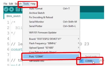
Select the Port if you don’t see the COM Port in your Arduino IDE, you need to install the FTDI Drivers: https://ftdichip.com/drivers/d2xx-drivers/
For Installation Guide,CLICK HERE
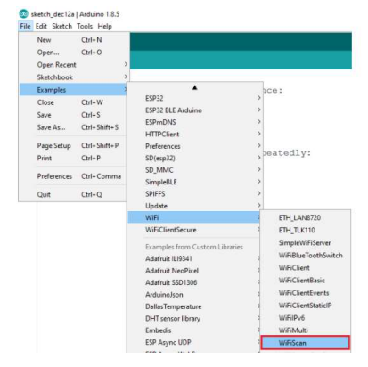
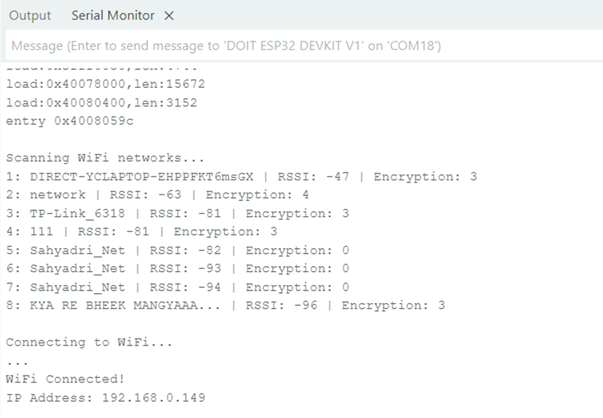
Step 3: Open the following example under File > Examples > WiFi (ESP32) > WiFiScan
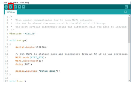
Step 4: A new sketch opens in your Arduino IDE:
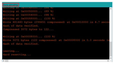
Step 5:Press the Upload button in the Arduino IDE. Wait a few seconds while the code
compiles and uploads to your board.
If everything went as expected, you should see a “Done uploading.” message.
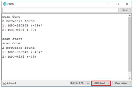
Step 6: Open the Arduino IDE Serial Monitor at a baud rate of 115200:
Step 7: Press the ESP32 on-board Reset button and you should see the networks available
near your ESP32:
NOTE:Before Uploading any codes to the Trainer Kit, make the below settings:
1. Make FTRX and FTTX pins of DIP2 HIGH
2. Make all pins of DIP1 HIGH
Installing Libraries
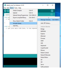
Step 1: To install a new library into your Arduino IDE. Open the IDE and click to the "Sketch" menu and then Include Library ![]() Manage Libraries.
Manage Libraries.
Step 2: Then the Library Manager will open and you will find a list of libraries that are already installed or ready for installation. In this example we will install the RTC library(i.e rtclib).Enter the library name to find it, click on it, then select the version of the library you want to install. Sometimes only one version of the library is available.Then click on install.
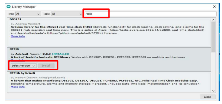
Step 3: Wait for the IDE to install the new library. Downloading may take time depending on your connection speed. Once it has finished, an Installed tag should appear next to the RTC library. Then click on close.
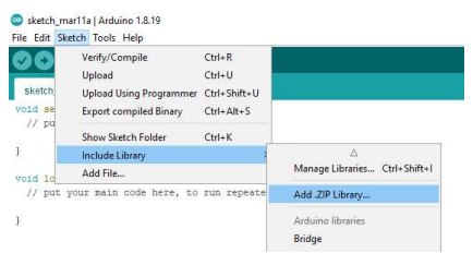
Another Method for installing and importing a .zip Library
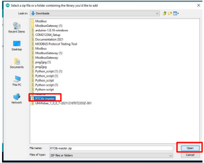
Step 1: Go to Google, search for the library(i.e rtclib) you want to install, click on download ZIP.

Step 2: In the Arduino IDE, go to Sketch > Include Library > Add .ZIP Library.
Step 3: Select the library you would like to add. Go to the .zip file's downloaded location and open it.
Libraries Link
- Keypad Library (keypad.h) DOWNLOAD HERE
- LCD Library (LiquidCrystal.h) DOWNLOAD HERE
- RTC Libraries (rtclib) DOWNLOAD HERE
- SD Card Libraries (FS.h) DOWNLOAD HERE
- OLED Libraries (Adafruit_GFX.h) DOWNLOAD HERE
- MQTT (PubSubClient.h) DOWNLOAD HERE
- JSON (WiFi.h) DOWNLOAD HERE
- OTA (WiFiClient.h) DOWNLOAD HERE
Blinking an LED
Aim:Interfacing LED’s with ESP32-Microcontroller.
Description:To learn how to programme an ESP32 Microcontroller to blink an LED by connecting an
LED’S to its digital pins.
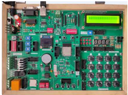
Hardware Requirement:ESP32 IoT Development Kit and FRC cable.
Schematic Diagram
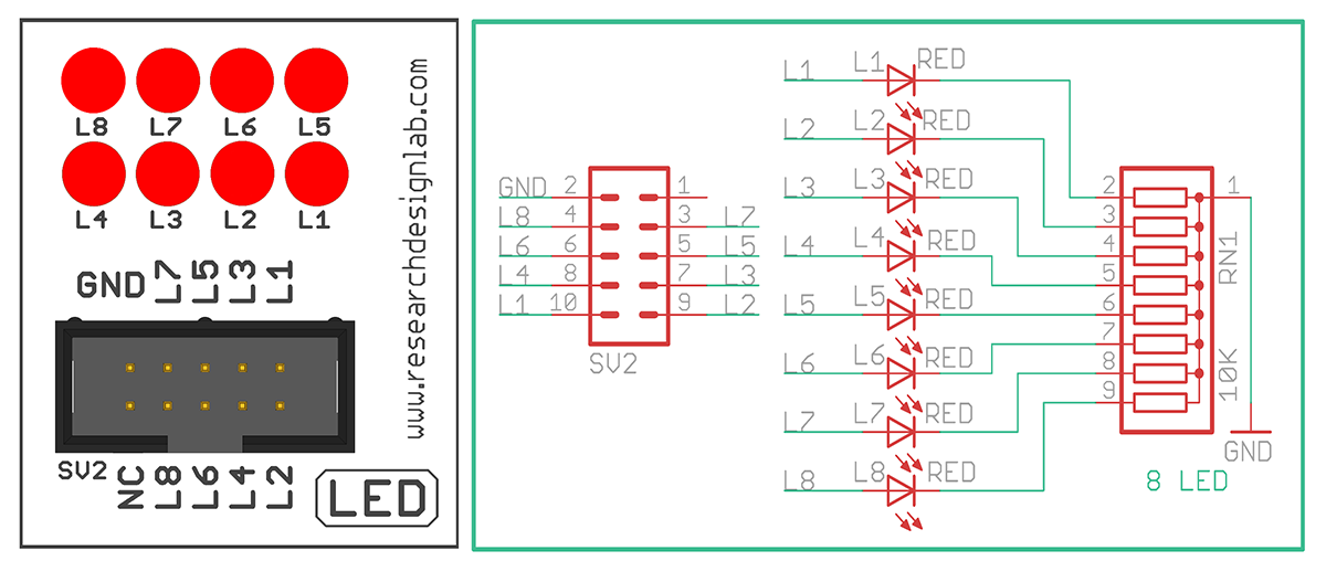
Procedure:
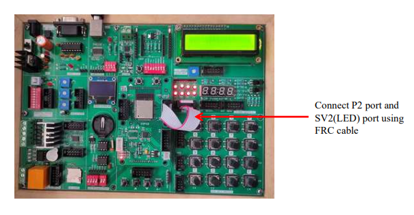
1. Connect the SV2 port (LED port) on the ESP32 board properly.
2. Connect the USB cable to the ESP32 board and to the computer.
3. Open Arduino IDE. Select ESP32 Board and choose the correct COM Port.
4. Write the blinking LED program and click Verify.
5. Click Upload to upload the program to the ESP32.
6. After uploading, the LED connected to SV2 port will start blinking.
Code
const int L1=23, L2=22, L3=21, L4=19, L5=18, L6=5, L7=17, L8=16; //initializing LED pins
void setup()
{
pinMode(L1, OUTPUT); // Set all Port P2 pins as output
pinMode(L2, OUTPUT);
pinMode(L3, OUTPUT);
pinMode(L4, OUTPUT);
pinMode(L5, OUTPUT);
pinMode(L6, OUTPUT);
pinMode(L7, OUTPUT);
pinMode(L8, OUTPUT);
}
void loop()
{
digitalWrite(L1, HIGH);
digitalWrite(L2, HIGH);
digitalWrite(L3, HIGH);
digitalWrite(L4, HIGH);
digitalWrite(L5, HIGH);
digitalWrite(L6, HIGH);
digitalWrite(L7, HIGH);
digitalWrite(L8, HIGH);
delay(2000);
digitalWrite(L1, LOW);
digitalWrite(L2, LOW);
digitalWrite(L3, LOW);
digitalWrite(L4, LOW);
digitalWrite(L5, LOW);
digitalWrite(L6, LOW);
digitalWrite(L7, LOW);
digitalWrite(L8, LOW);
delay(2000);
}
Controlling LED Using Switch
Aim: Controlling LED using a DIP Switch.
Description: Understanding the working of DIP switch. When the switch is turned on, the LED
is turned on, and when it is turned off, the LED is turned off.
Hardware Requirement: ESP32 IoT Development Kit and FRC Cable
Schematic Diagram
Procedure:
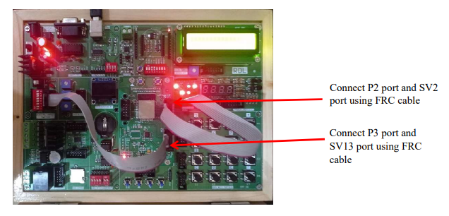
1. Connect P3 port and SV13 (Digital Input Switch) port and connect P2 port and SV2(LED) port using FRC cable as shown above.
2. Connect the USB cable to the board.
3. Open Arduino IDE .Select DOIT ESP32 DEVKIT V1in boards and select COM port.
4. Now write the program, verify and Upload it.
5. Now, when the switch is turned on, LED gets On.
Code
// LED Pins
const int Led[8] = {23, 22, 21, 19, 18, 5, 17, 16};

// Switch Pins (define properly)
const int Switch[8] = {13, 12, 14, 27, 26, 25, 33, 32};

void setup()
{
  for(int i = 0; i < 8; i++)
  {
    pinMode(Led[i], OUTPUT);
    pinMode(Switch[i], INPUT);   // Use INPUT_PULLUP if needed
  }
}

void loop()
{
  for(int i = 0; i < 8; i++)
  {
    digitalWrite(Led[i], digitalRead(Switch[i]));
  }
}
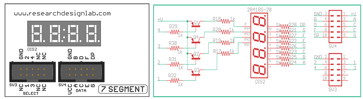
Seven Segment Displays
Aim: Interfacing ESP32-Microcontroller with seven segment display.
Description: To display numbers in the seven segment display.
Hardware Requirement: ESP32-Microcontroller Development board and FRC Cables.
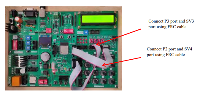
Schematic Diagram
Procedure:
1.Connect P2 port and SV4 (Data) port and connect P3 port and SV3 (Select) port using FRC cable as shown above.
2. Connect the USB cable to the board.
3. Open Arduino IDE .Select DOIT ESP32 DEVKIT V1 in boards and select COM port.
4. Write the program, verify and Upload it.
5. Now you can see that number starts displaying on the seven segments on the ESP32
development board.
Code
const int sel1=25, sel2=26, sel3=2, sel4=4; //initializing selection pins -Port P3
const int a=16 ,b=17, c=5, d=18, e=19, f=21, g=22, dp=23; //initializing data pins -Port P2
void setup()
{
pinMode(sel1,OUTPUT); //declaring Selection Pins as output
pinMode(sel2,OUTPUT);
pinMode(sel3,OUTPUT);
pinMode(sel4,OUTPUT);
digitalWrite(sel1,LOW); //selecting all 4 digits of 7-Segment display by making it LOW
digitalWrite(sel2,LOW);
digitalWrite(sel3,LOW);
digitalWrite(sel4,LOW);
pinMode(a,OUTPUT); //declaring data pins as output
pinMode(b,OUTPUT);
pinMode(c,OUTPUT);
pinMode(d,OUTPUT);
pinMode(e,OUTPUT);
pinMode(f,OUTPUT);
pinMode(g,OUTPUT);
pinMode(dp,OUTPUT);
delay(100);
}
void loop()
{
 // print 0
digitalWrite(a,LOW);
digitalWrite(b,LOW);
digitalWrite(c,LOW);
digitalWrite(d,LOW);
digitalWrite(e,LOW);
digitalWrite(f,LOW);
digitalWrite(g,HIGH);
digitalWrite(dp,LOW);
delay(2000);
// print 1
digitalWrite(a,HIGH);
digitalWrite(b,LOW);
digitalWrite(c,LOW);
digitalWrite(d,HIGH);
digitalWrite(e,HIGH);
digitalWrite(f,HIGH);
digitalWrite(g,HIGH);
digitalWrite(dp,HIGH);
delay(2000);
// print 2
digitalWrite(b,LOW);
digitalWrite(c,HIGH);
digitalWrite(d,LOW);
digitalWrite(e,LOW);
digitalWrite(f,HIGH);
digitalWrite(g,LOW);
digitalWrite(dp,LOW);
delay(2000);
// print 3
digitalWrite(a,LOW);
digitalWrite(b,LOW);
digitalWrite(c,LOW);
digitalWrite(d,HIGH);
digitalWrite(e,HIGH);
digitalWrite(f,LOW);
digitalWrite(g,LOW);
digitalWrite(dp,LOW);
delay(2000);
// print 4
digitalWrite(a,HIGH);
digitalWrite(b,LOW);
digitalWrite(c,LOW);
digitalWrite(d,HIGH);
digitalWrite(e,LOW);
digitalWrite(f,HIGH);
digitalWrite(g,LOW);
digitalWrite(dp,LOW);
delay(2000);
// print 5
digitalWrite(a,LOW);
digitalWrite(b,HIGH);
digitalWrite(c,LOW);
digitalWrite(d,LOW);
digitalWrite(e,HIGH);
digitalWrite(f,LOW);
digitalWrite(g,LOW);
digitalWrite(dp,LOW);
delay(2000);
// print 6
digitalWrite(a,LOW);
digitalWrite(b,HIGH);
digitalWrite(c,LOW);
digitalWrite(d,LOW);
digitalWrite(e,LOW);
digitalWrite(f,LOW);
digitalWrite(g,LOW);
digitalWrite(dp,LOW);
delay(2000);

// print 7
digitalWrite(a,LOW);
digitalWrite(b,LOW);
digitalWrite(c,LOW);
digitalWrite(d,HIGH);
digitalWrite(e,HIGH);
digitalWrite(f,HIGH);
digitalWrite(g,HIGH);
digitalWrite(dp,HIGH);
delay(2000);

// print 8
digitalWrite(a,LOW);
digitalWrite(b,LOW);
digitalWrite(c,LOW);
digitalWrite(d,LOW);
digitalWrite(e,LOW);
digitalWrite(f,LOW);
digitalWrite(g,LOW);
digitalWrite(dp,LOW);
delay(2000);

 // print 9
digitalWrite(a,LOW);
digitalWrite(b,LOW);
digitalWrite(c,LOW);
digitalWrite(d,LOW);
digitalWrite(e,HIGH);
digitalWrite(f,LOW);
digitalWrite(g,LOW);
digitalWrite(dp,LOW);
delay(2000);
}
Hex Keypad
Aim: To interface 4x4 Hex Keypad with ESP32-Microcontroller module.
Description: To display the pressed key on the serial monitor.
Hardware Requirement: ESP32 - Microcontroller Development board and FRC Cable.
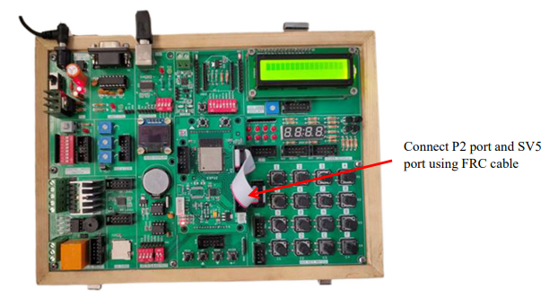
Schematic Diagram

Procedure:
1. Connect P2 port and SV5(4*4 Key Matrix) port using FRC cable as shown above.
2. Connect the USB cable to the board.
3. Open Arduino IDE .Select DOIT ESP32 DEVKIT V1 in boards and select COM port.
4. Write the program, verify and Upload it.
5. After uploading is done open serial monitor to observe the output
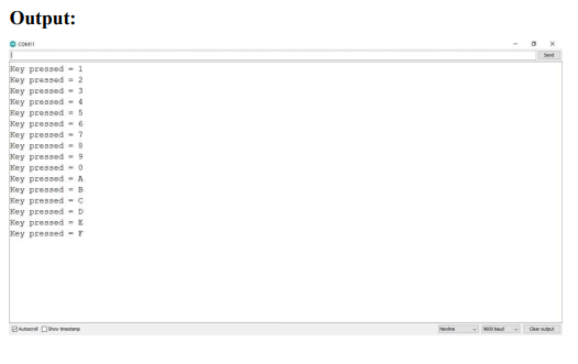
6. On your serial monitor, the number appears for each switch pressed.
Code
#include <Keypad.h>
char keys[4][4]={ {'1','2','3','4'},{'5','6','7','8'},{'9','0','A','B'},
{'C','D','E','F'}}; //defining
byte rowPin[4]={16,17,5,18}; //declaring the rows and column pins (Port P2)
byte colPin[4]={19,21,22,23};
// Creating 4X4 Keypad
Keypad keypad=Keypad(makeKeymap(keys),rowPin,colPin,4,4);
void setup()
{
Serial.begin(9600);
}
void loop()
{
//This function will fetch the character being pressed
char pressed=keypad.getKey();
if(pressed)
{
Serial.print("Key pressed = ");
Serial.println(pressed);
}
delay(500);
}
Output
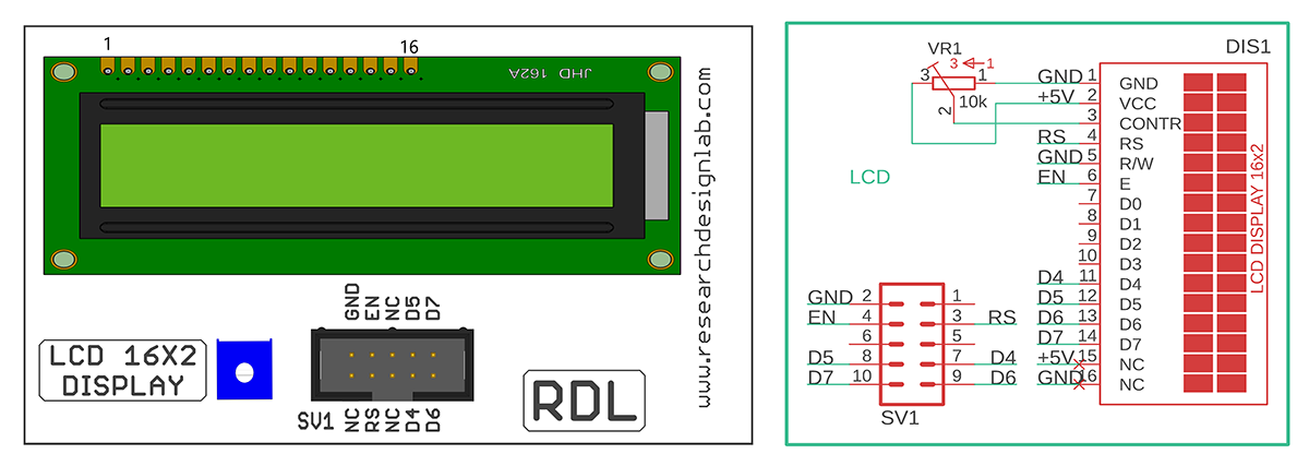
Liquid Crystal Display (LCD)
Aim: To interface LCD display with ESP32-Microcontroller module.
Description: To display the message on the LCD screen.
Hardware Requirement: ESP32-Microcontroller Development board and FRC Cable.
Schematic Diagram
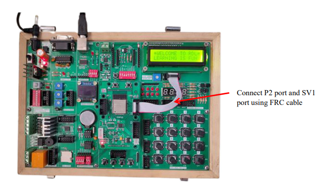
Procedure:
1. Connect P2 port and SV1(LCD 16*2 Display) port using FRC cable as shown above.
2. Connect the USB cable to the board.
3. Open Arduino IDE .Select DOIT ESP32 DEVKIT V1 in boards and select COM port.
4. Write the program, verify and Upload it.
5. Now you can see the output on LCD.
Code
#include <LiquidCrystal.h> // Include the LCD library
LiquidCrystal lcd(16,17,19,21,22,23); //Port P2 Mapping the pins with library
void setup()
{
Serial.begin(9600); //Baud Rate
lcd.begin(16,2); //initializing 16X2 LCD display
}
void loop()
{
lcd.setCursor(0,0); //first line in display
lcd.print("*WELCOME TO RDL*");
delay(3000);
//lcd.clear();
lcd.setCursor(0,1); //second line in display
lcd.print("LEARNING IS FUN");
delay(3000);
lcd.clear();
}
IR (Infrared) Sensor
Aim: To Interfacing IR sensor with ESP32-Microcontroller module
Description: To learn how to read values from an IR sensor using ESP32 - Microcontroller.
Hardware Requirement: ESP32 - Microcontroller Development board, IR sensor, F-F Patch Chords.
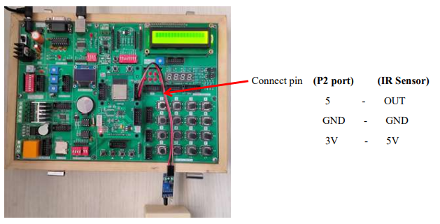
Procedure:
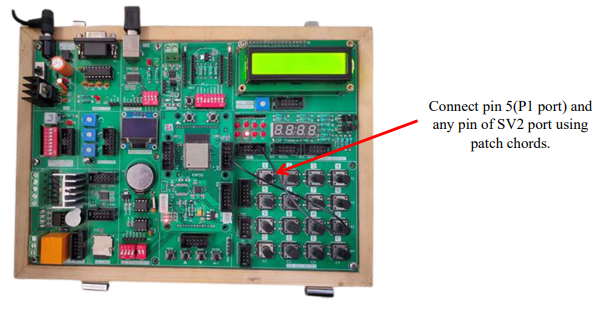
1. Connect P2 port pins (5, GND, 3V) to IR Sensor pins (OUT, GND, 5V) using patch chords as shown above.
2. Connect the USB cable to the board.
3. Open Arduino IDE .Select DOIT ESP32 DEVKIT V1 in boards and select COM port.
4. Write the program, verify and Upload it.
5. Now you can see the output on the serial monitor
Code
const int proximity=5; //pin5 of port P1 connected to IR sensor
int value=0;
void setup() {
Serial.begin(9600);
pinMode(proximity, INPUT); //declared as input
delay(100);
}
void loop() {
value=digitalRead(proximity); // storing sensor data in a variable.
delay(1000);
if(!value) //check for an obstacle if present.
{
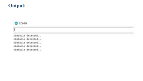
Serial.println("obstacle detected.."); //display this message when obstacle detects
}
}
Output
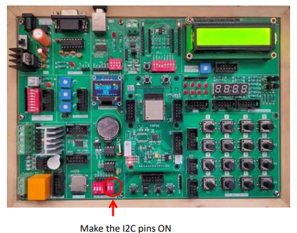
RTC (Real Time Clock)
Aim: Interfacing Real Time Clock module with ESP32-Microcontroller module.
Description: To display Date and Time on the serial monitor using ESP 32 microcontroller development board.
Hardware Requirement: ESP32 - Microcontroller Development board and RTC Battery.
Schematic Diagram
Procedure:
1. Connect the USB cable to the board.
2. Open Arduino IDE. Select DOIT ESP32 DEVKIT V1 in boards and select COM port.
3. Write the program, verify and Upload it.
4. Open the serial monitor to observe the output.
Code
#include "Wire.h"
#define DS1307_I2C_ADDRESS 0x68
// Convert normal decimal numbers to binary coded decimal
byte decToBcd(byte val){
return( (val/10*16) + (val%10) );
}
// Convert binary coded decimal to normal decimal numbers
byte bcdToDec(byte val){
return( (val/16*10) + (val%16) );
}
void setup(){
Wire.begin();
Serial.begin(9600);
delay(1000);
 // set the initial time here:
setDS1307time(00,50,12,2,22,3,21); // DS1307 seconds, minutes, hours, day, date, month,
year
delay(1000);
}
void setDS1307time(byte second, byte minute, byte hour, byte dayOfWeek, byte
dayOfMonth, byte month, byte year){
// sets time and date data to DS1307
Wire.beginTransmission(DS1307_I2C_ADDRESS);
Wire.write(0); // set next input to start at the seconds register
Wire.write(decToBcd(second)); // set seconds
Wire.write(decToBcd(minute)); // set minutes
Wire.write(decToBcd(hour)); // set hours
Wire.write(decToBcd(dayOfWeek)); // set day of week (1=Sunday, 7=Saturday)
Wire.write(decToBcd(dayOfMonth)); // set date (1 to 31)
Wire.write(decToBcd(month)); // set month
Wire.write(decToBcd(year)); // set year (0 to 99)
Wire.endTransmission();
}
void readDS1307time(byte *second, byte *minute, byte *hour,
byte *dayOfWeek, byte *dayOfMonth, byte *month, byte *year)
{
Wire.beginTransmission(DS1307_I2C_ADDRESS);
Wire.write(0); // set DS1307 register pointer to 00h
Wire.endTransmission();
delay(100);
Wire.requestFrom(DS1307_I2C_ADDRESS, 7);
// request seven bytes of data from DS1307 starting from register 00h
*second = bcdToDec(Wire.read() & 0x7f);
*minute = bcdToDec(Wire.read());
*hour = bcdToDec(Wire.read() & 0x3f);
*dayOfWeek = bcdToDec(Wire.read());
*dayOfMonth = bcdToDec(Wire.read());
*month = bcdToDec(Wire.read());
*year = bcdToDec(Wire.read());
Wire.endTransmission();
}
void displayTime(){
byte second, minute, hour, dayOfWeek, dayOfMonth, month, year;
// retrieve data from DS1307
readDS1307time(&second, &minute, &hour, &dayOfWeek, &dayOfMonth, &month,
&year);
// send it to the serial monitor
Serial.print(hour, DEC);
// convert the byte variable to a decimal number when displayed
Serial.print(":");
if (minute<10){
Serial.print("0");
}
Serial.print(minute, DEC);
Serial.print(":");
if (second<10){
Serial.print("0");
}
Serial.print(second, DEC);
Serial.print(" ");
Serial.print(dayOfMonth, DEC);
Serial.print("/");
Serial.print(month, DEC);
Serial.print("/");
Serial.print(year, DEC);
Serial.print(" Day of week: ");
switch(dayOfWeek){
case 1:
Serial.println("Sunday");
break;
case 2:
Serial.println("Monday");
break;
case 3:
Serial.println("Tuesday");
break;
case 4:
Serial.println("Wednesday");
break;
case 5:
Serial.println("Thursday");
break;
case 6:
Serial.println("Friday");
break;
case 7:
Serial.println("Saturday");
break;
}
}
void loop(){
displayTime(); // display the real-time clock data on the Serial Monitor,
delay(1000); // every second
}
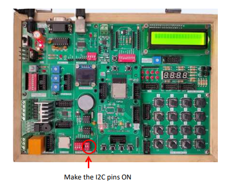
ADC
Aim: To Interface ADC with ESP 32- Microcontroller Module.
Description: To learn how to read ADC values using ESP32-Microcontroller.
Hardware Requirement: ESP32-Microcontroller Development board and FRC Cable.
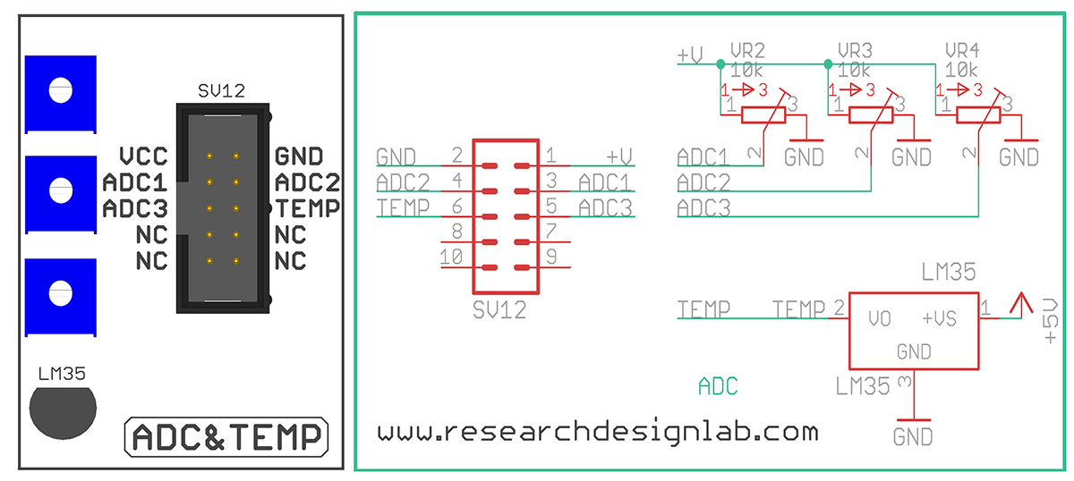
Schematic Diagram
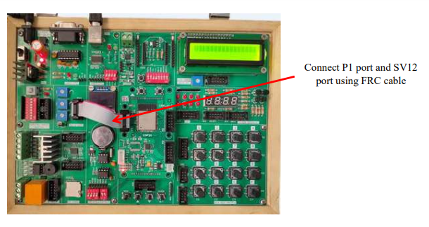
Procedure:
1. Connect P1 port and SV12 (ADC & Temp) port using FRC cable as shown above.
2. Connect the USB cable to the board.
3. Open Arduino IDE. Select DOIT ESP32 DEVKIT V1 in boards and select COM port.
4. Write the program, verify and Upload it.
5. Open the serial monitor to observe the output.
Code
const int adc1=32;
const int adc2=33;
const int adc3=36;
int value1=0, value2=0, value3=0;
float res1=0, res2=0, res3=0;
void setup() {
Serial.begin(115200);
pinMode(adc1, INPUT); // Pins Port1 Connected to ADC Knobs
pinMode(adc2, INPUT);
pinMode(adc3, INPUT);
delay(500);
}
void loop() {
delay(1000);
value1=analogRead(adc1);
value2=analogRead(adc2);
value3=analogRead(adc3);
res1=float((value1*3.3)/4095); //3.3v is maximum voltage applied as a input
res2=float((value2*3.3)/4095); //it is 12bit ADC hence dividing by 4095 gives actual
voltage
res3=float((value3*3.3)/4095);
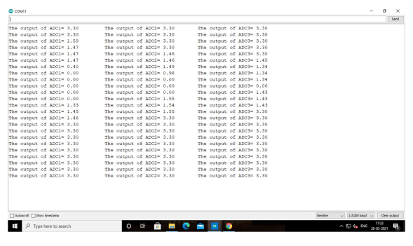
Serial.print("The output of ADC1= ");
Serial.print(res1);
delay(500);
Serial.print("\t The output of ADC2= ");
Serial.print(res2);
delay(500);
Serial.print("\t The output of ADC3= ");
Serial.println(res3);
delay(500);
}
Output
L298 Motor
Aim: To Interface L298 Motor with ESP32 - Microcontroller Board.
Description: This experiment shows how to rotate the L298 Motor clockwise and anticlockwise using
ESP32-Microcontroller.
Hardware required: ESP32-Microcontroller Development board, L298 Motor and FRC Cable.
Schematic Diagram
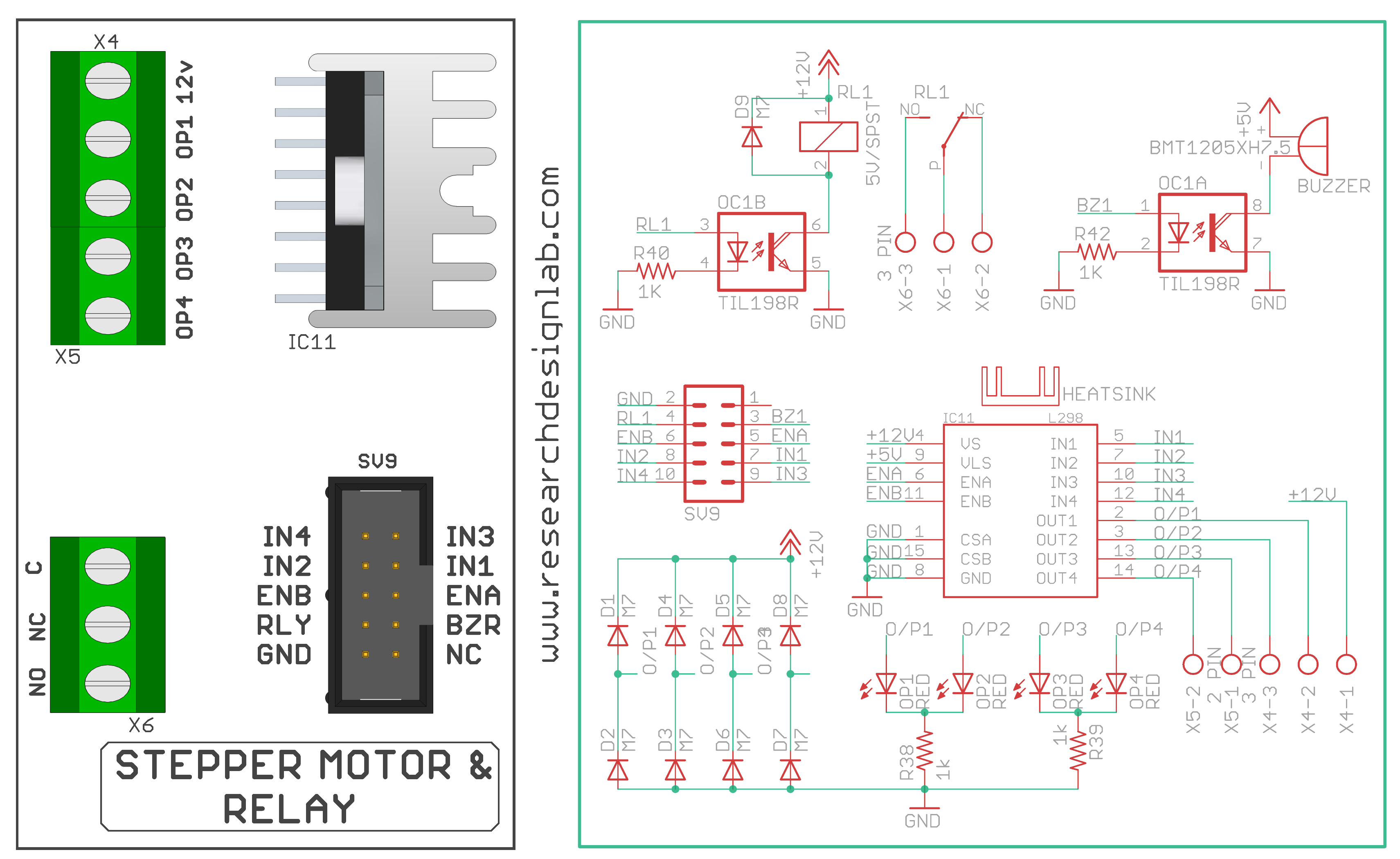
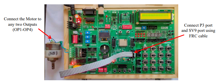
Procedure:
1. Connect P3 port and SV9 port using FRC cable.
2. Connect the USB cable to the board.
3. Open Arduino IDE. Select DOIT ESP32 DEVKIT V1 in boards and select COM port.
4. Write the program, verify and Upload it.
Code
const int En1=2,En2=4; //initializing enable pins
const int in1=27, in2=13, in3=14, in4=15; //initializing input pins
int count=0;
void setup()
{
 // channel A
 pinMode(En1,OUTPUT);
 pinMode(in1,OUTPUT);
 pinMode(in2,OUTPUT);
 // channel B
 pinMode(En2,OUTPUT);
 pinMode(in3,OUTPUT);
 pinMode(in4,OUTPUT);
}
void loop() {

 digitalWrite(En1,HIGH); //enabling motor1
 digitalWrite(En2,LOW);

 // Motor 1 clockwise rotation
 while(count!=100) //motor1 keep rotating for 1 minute in clockwise direction
 {
 digitalWrite(in1,HIGH);
 digitalWrite(in2,LOW);
 delay(600);
 count++;
 }
count=0;

 //Motor1 anticlockwise rotation
 while(count!=100) //motor1 keep rotating for 1 minute in anti-clockwise direction
 {
 digitalWrite(in1,LOW);
 digitalWrite(in2,HIGH);
 delay(600);
 count++;
 }
count=0;
 digitalWrite(in1,LOW); //to stop motor1
 digitalWrite(in2,LOW);
 delay(100);
 digitalWrite(En1,LOW); //enabling Motor 2
 digitalWrite(En2,HIGH);
// Motor 2 clockwise rotation
 while(count!=100) //motor2 keep rotating for 1 minute in clockwise direction
 {
 digitalWrite(in3,HIGH);
 digitalWrite(in4,LOW);
 delay(600);
 count++;
 }
 count=0;

 //Motor2 anticlockwise rotation

 while(count!=100) //motor2 keep rotating for 1 minute in anti-clockwise direction
 {
 digitalWrite(in3,LOW);
 digitalWrite(in4,HIGH);
 delay(600);
 count++;
 }
 //to stop motor2
 digitalWrite(in3,LOW); //to stop motor2
 digitalWrite(in4,LOW);
 delay(100);
}
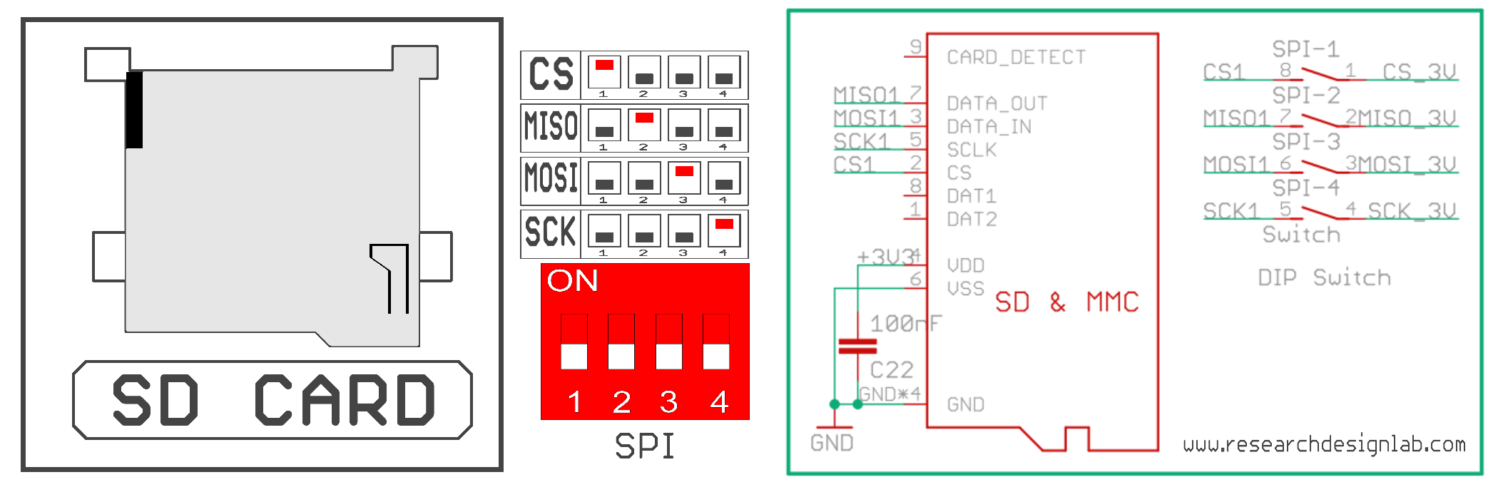
SD Card
Aim: Interfacing SD card with ESP32 - Microcontroller Board to list the directories stored in memory card.
Description: To read the stored directories in SD card using ESP 32 microcontroller development board.
Hardware Requirement: ESP32 - Microcontroller Development board and SD Card.
Schematic Diagram
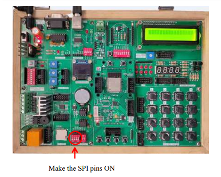
Procedure:
1. Insert the SD Card in the slot given in the board.
2. Connect the USB cable to the board.
3. Open Arduino IDE. Select DOIT ESP32 DEVKIT V1 in boards and select COM port.
4. Write the program, verify and Upload it.
5. Open the serial monitor to observe the output.
Code
		    #include "FS.h"
		  #include "SD.h"
		  #include "SPI.h"
		  void writeFile(fs::FS &fs, const char * path, const char * message){
		  Serial.printf("Writing file: %s\n", path);
		  File file = fs.open(path, FILE_WRITE);
 if(!file){
 Serial.println("Failed to open file for writing");
 return;
 }
 if(file.print(message)){
 Serial.println("File written");
 } else {
 Serial.println("Write failed");
 }
 file.close();
}
void appendFile(fs::FS &fs, const char * path, const char * message){
 Serial.printf("Appending to file: %s\n", path);
 File file = fs.open(path, FILE_APPEND);
 if(!file){
 Serial.println("Failed to open file for appending");
 return;
 }
 if(file.print(message)){
 Serial.println("Message appended");
 } else {
 Serial.println("Append failed");
 }
 file.close();
}
void readFile(fs::FS &fs, const char * path){
 Serial.printf("Reading file: %s\n", path);
 File file = fs.open(path);
 if(!file){
 Serial.println("Failed to open file for reading");
 return;
 }
 Serial.print("Read from file: ");
 while(file.available()){
 Serial.write(file.read());
}
file.close();
}
void renameFile(fs::FS &fs, const char * path1, const char * path2)
{
Serial.printf("Renaming file %s to %s\n", path1, path2);
if (fs.rename(path1, path2))
{
Serial.println("File renamed");
}
else
{
Serial.println("Rename failed");
}
}
void deleteFile(fs::FS &fs, const char * path)
{
Serial.printf("Deleting file: %s\n", path);
if(fs.remove(path)){
Serial.println("File deleted");
} else {
Serial.println("Delete failed");
}
}
void setup(){
Serial.begin(115200);
if(!SD.begin())
{
Serial.println("Card Mount Failed");
return;
}
uint8_t cardType = SD.cardType();
if(cardType == CARD_NONE){
Serial.println("No SD card attached");
return;
}
Serial.print("SD Card Type: ");
if(cardType == CARD_MMC)
{
Serial.println("MMC");
} else if(cardType == CARD_SD){
Serial.println("SDSC");
} else if(cardType == CARD_SDHC){
Serial.println("SDHC");
} else {
  Serial.println("UNKNOWN");
}
uint64_t cardSize = SD.cardSize() / (1024 * 1024);
Serial.printf("SD Card Size: %lluMB\n", cardSize);
writeFile(SD, "/hello.txt", "Hello ");
appendFile(SD, "/hello.txt", "World!\n");
readFile(SD, "/hello.txt");
deleteFile(SD, "/foo.txt");
renameFile(SD, "/hello.txt", "/foo.txt");
readFile(SD, "/foo.txt");
// testFileIO(SD, "/test.txt");
Serial.printf("Total space: %lluMB\n", SD.totalBytes() / (1024 * 1024));
Serial.printf("Used space: %lluMB\n", SD.usedBytes() / (1024 * 1024));
}
void loop()
{

}
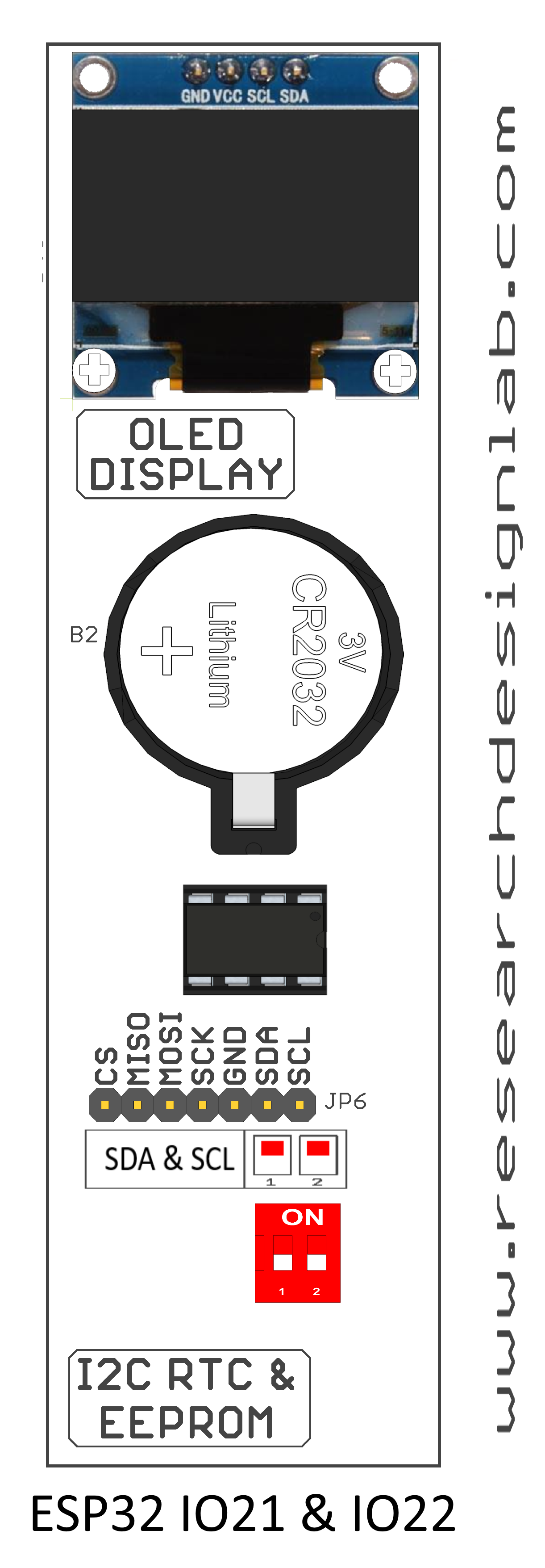
OLED
Aim: To Interface OLED Display with ESP32 - Microcontroller Board.
Description: To display message on OLED screen.
Hardware Requirement: ESP32 - Microcontroller Development board
Schematic Diagram
Procedure:
1. Connect the USB cable to the board.
2. Open Arduino IDE. Select DOIT ESP32 DEVKIT V1 in boards and select COM port.
3. Write the program, verify and Upload it.
4. Now you can see the output displaying the message on OLED of ESP32 microcontroller board.
Code
#include <SPI.h>
#include <Wire.h>
#include <Adafruit_GFX.h>
#include <Adafruit_SSD1306.h>
#define SCREEN_WIDTH 128 // OLED display width, in pixels
#define SCREEN_HEIGHT 32 // OLED display height, in pixels
#define OLED_RESET 4 // Reset pin
#define SCREEN_ADDRESS 0x3C //0x3C for 128x32pixels OLED
Adafruit_SSD1306 display (SCREEN_WIDTH, SCREEN_HEIGHT, &Wire,
OLED_RESET);
void setup() {
 Serial.begin(9600);
 if(!display.begin(SSD1306_SWITCHCAPVCC, SCREEN_ADDRESS)) //
SSD1306_SWITCHCAPVCC = generate display voltage from 3.3V internally
 {
 Serial.println(F("SSD1306 allocation failed"));
 for(;;); // Don't proceed, loop forever
 }

}
void loop() {
 text();
 display.invertDisplay(true);
 delay(2000);
 display.invertDisplay(false);
 delay(2000);
}
void text(void) {
 display.clearDisplay();
 display.setTextSize(2);
 display.setTextColor(SSD1306_WHITE); // Draw white text
 display.setCursor(5,3); //setting cursor on X Y plane
 display.print(F("Welcome To ...RDL..."));
 display.setTextColor(SSD1306_BLACK, SSD1306_WHITE); // Draw 'inverse' text

 display.display();
 delay(2000);
}
Temperature Sensor
Aim: To extract information from temperature sensor.
Description:To learn how to read values from a temperature sensor using ESP32 - Microcontroller.
Hardware Requirement:ESP32 - Microcontroller Development board .
Schematic Diagram
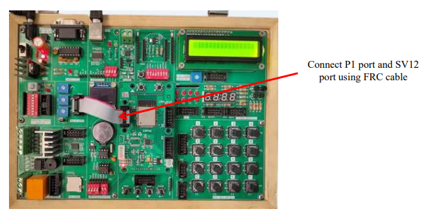
Procedure:
1. Connect P1 port and SV12 port using FRC cable as shown above
2. Connect the USB cable to the board
3. Open Arduino IDE. Select DOIT ESP32 DEVKIT V1 in boards and select COM port.
4. Write the program, verify and Upload it.
5. Now you can see the output on the serial monitor
Code
const int tempPin = 39; // pin 33 of port P1 connected to LM35 output

int Value;
double milivlt,Cel,Far;

void setup()
{
Serial.begin(9600);
}

void loop()
{
 Value = analogRead(tempPin); //read sensor output value
 milivlt = (Value / 2048.0) * 3300; // converting it to millivots.
 Cel = milivlt * 0.1; // calculating temperature in Celsius
 Far = (Cel * 1.8) + 32; // convert from C to Fahrenheit
 Serial.print(" Temperature in Celsius = ");
 Serial.print(Cel);
 Serial.print("*C");
 Serial.print("\t Temperature in Fahrenheit = ");
 Serial.print(Far);
 Serial.println("*F");
 delay(2000); //check the temperature every 2 second
}
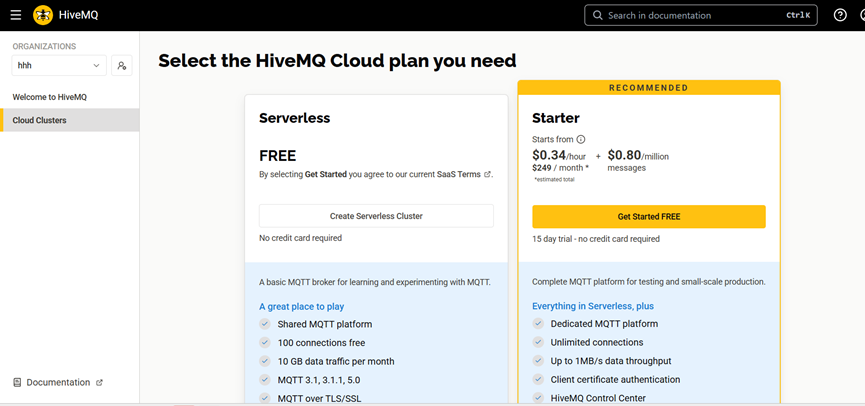
MQTT Publish and Subscribe
Aim: To interface Wi-Fi module with Cloud to Publish and Subscribe data using RDL ESP32 Development board
Description: Interfacing Wi-Fi module with the cloud MQTT to Publish and Subsribe data using ESP32
microcontroller.
Hardware Requirement: ESP32 - Microcontroller Development board
Procedure:
Create a HiveMQ Cloud Account – Go to the HiveMQ Cloud website and register for a free account.(https://www.hivemq.com/mqtt/public-mqtt-broker/)
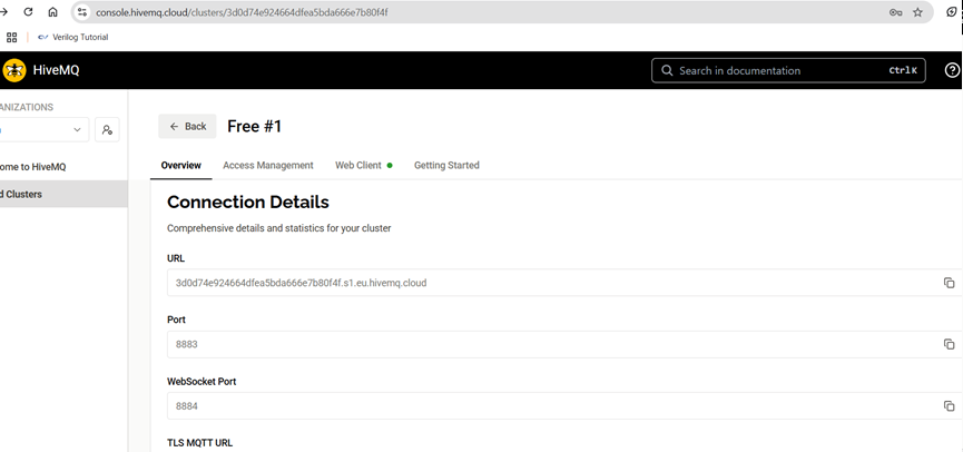
2. Create and Deploy a Cluster – Create a new Free Tier cluster, choose a region, and wait until the cluster status shows Running.
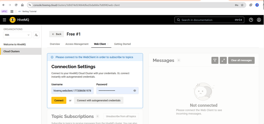
3. Create MQTT Credentials – In the Access Management section, create a username and password for authentication.
4. Copy Broker Details – Note down the Cluster URL (Broker address) and secure port number (8883).
5. Configure ESP32 WiFi – In your ESP32 code, add your WiFi SSID and password, and connect to a 2.4GHz WiFi network.
6. Configure MQTT in ESP32 – Use WiFiClientSecure, set port 8883, add espClient.setInsecure();, and provide the broker URL, username, and password in the code.
7.Upload and Test Communication – Upload the code to ESP32 and verify connection using Serial Monitor, then publish and subscribe to topics using HiveMQ Web Client or ESP32 to confirm successful communication.

Code
#include <WiFi.h>
#include <PubSubClient.h>
const char* ssid = "J7 pro";
const char* password = "fzao2408";
/* Details from the instance created */
const char* mqttServer = "m16.cloudmqtt.com";
const int mqttPort = 18215;
const char* mqttUser = "ofmydmjh";
const char* mqttPassword = "c5g0IEjTCGRn";
WiFiClient espClient;
PubSubClient client(espClient);
void setup(void)
{
Serial.begin(115200);
WiFi.begin(ssid, password);
/* Connecting ESP8266 to WiFi */
while (WiFi.status() != WL_CONNECTED)
{
delay(500);
Serial.write('.');
}
Serial.println("Connected to the WiFi network");
client.setServer(mqttServer, mqttPort);
client.setCallback(callback);
/* Connecting to CloudMqtt */
while (!client.connected())
{
Serial.println("Connecting to MQTT...");
if (client.connect("ESP32Client", mqttUser, mqttPassword ))
{
Serial.println("connected");
}
else
{
Serial.print("failed with state ");
Serial.print(client.state());
delay(2000);
}
}
/* Sending message to Topic "test1" */
client.publish("Sub", "Hello from RDL_IOT");
client.subscribe("test"); //Receives message sent to the topic "test"
}
/* This function is used to print the incoming data sent to the topic "test" */
void callback(char* topic, byte* payload, unsigned int length)
{
uint8_t s;
Serial.print("Message arrived in topic: ");
Serial.println(topic);
Serial.print("Message:");
for (int i = 0; i < length; i++)
{
s= payload[i];
Serial.write(s);
}
}
void loop(void)
{
client.loop();
}
Parsing JSON
Aim: To interface Wi-Fi module to parse JSON messages using ESP32 Development board.
Description:To explain how to parse JSON messages with the ESP32.
Hardware Requirement: ESP32 - Microcontroller development board.
Procedure:
1. Firstly you need a website where your ESP32 can send data.
2. If you already have a website (like iotpi.in), then use that website’s hosting account.
3. If you do NOT have a website, go to a free hosting site like 000webhost or InfinityFree and create a free account.
4. After creating the account, create a new website (it will give you a free domain name).
5. Upload your PHP file (like postgastempinsert.php) to that website using the file manager.
6. Make sure the website link opens properly in the browser.
7. Now use that website address in your ESP32 code and upload the program.
Code
/*
 * This sketch sends data via HTTP GET requests to data.sparkfun.com service.
 * You need to get streamId and privateKey at data.sparkfun.com and paste them
 * below. Or just customize this script to talk to other HTTP servers.
 *
 */
#include <WiFi.h>
/* type your username */
char ssid[] = "your ssid";
/* type your password */
char password[] = "your password";
const char* host = "iotpi.in";
const char* streamId = "....................";
const char* privateKey = "....................";
WiFiClient esp32client;
void setup(void)
{
 Serial.begin(115200);
 delay(10);
 /* We start by connecting to a WiFi network */
 Serial.println();
 Serial.println();
 Serial.print("Connecting to ");
 Serial.println(ssid);
 /* Explicitly set the ESP32 to be a WiFi-client, otherwise, it by default,
 would try to act as both a client and an access-point and could cause
 network-issues with your other WiFi-devices on your WiFi-network. */

 WiFi.begin(ssid, password);
 while (WiFi.status() != WL_CONNECTED)
 {
 delay(500);
 Serial.print(".");
 }
 Serial.println("");
 Serial.println("WiFi connected");
 Serial.println("IP address: ");
 Serial.println(WiFi.localIP());
 }
int value = 0;
void loop(void)
{
String url="/VCET/post/postgastempinsert.php?";
String jason_string="";
char cmd=0;
while(cmd!=13)
{
  if (Serial.available())
  {
  cmd=Serial.read();
  if(cmd!=13)
  jason_string+=cmd;
  }
  }
 while(Serial.available()>0) {Serial.read();}
 Serial.print("connecting to ");
 Serial.println(host);

 /* Use WiFiClient class to create TCP connections */
 const int httpPort = 80;
 if (!esp32client.connect(host, httpPort))
  {
  Serial.println("connection failed");
  return;
  }
 /* We now create a URI for the request */
 Serial.print("Requesting URL:");
 Serial.println(url);
 esp32client.print(String("POST ") + url + " HTTP/1.0\r\n" +
  "Host: " + host + "\r\n" +
  "Accept: *" + "/" + "*\r\n" +
  "Content-Length: " + jason_string.length() + "\r\n" +
  "Content-Type: application/json\r\n" +
  "\r\n" + jason_string
  + "\r\n");
 unsigned long timeout = millis();
 while (esp32client.available() == 0) {
 if (millis() - timeout > 5000) {
 Serial.println(">>> Client Timeout !");
 esp32client.stop();
 return;
 }
 }

 /* Read all the lines of the reply from server and print them to Serial */
 while(esp32client.available()){
 String line = esp32client.readStringUntil('\r');
 Serial.print(line);
 }
 Serial.println();
 }
Output
1. Open serial monitor you can see Wi-Fi connected along with IP address Insert { “gas”:”40” , “temperature”:”70” } in the serial monitor and press enter.
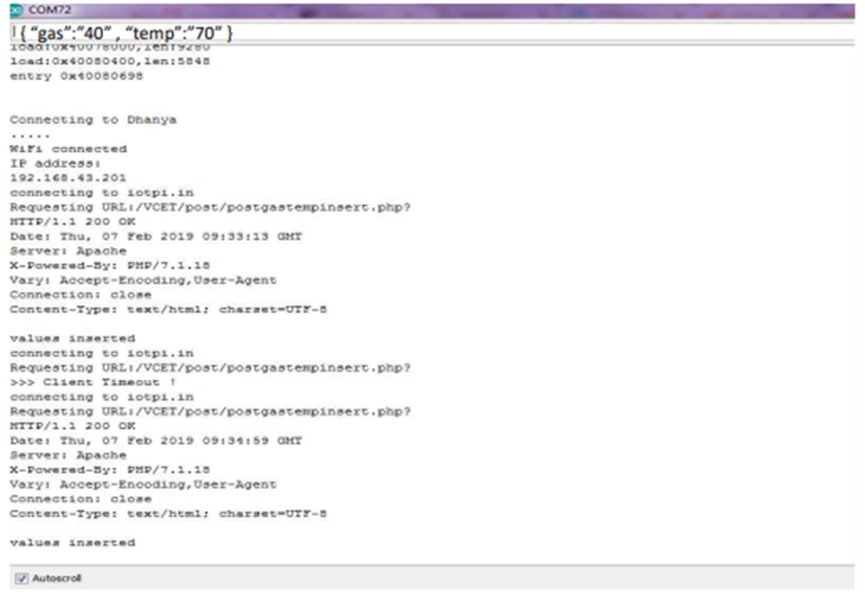
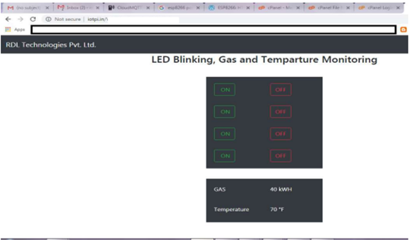
2. Enter your JSON Url (Ex:iobbpi.in/Vbcdbf/pabc/postportal.html) in your browser.
FTP (File Transfer Protocol)
Aim: To interface wifi module to upload a file to a FTP Server using ESP32 Development board.
Description: Interfacing wifi module to upload a file to a FTP Serve using ESP32 microcontroller.
Hardware Requirement: ESP32 - Microcontroller Development board.
Procedure:
1. Connect the USB cable to the ESP32 development board.
2. Open Arduino IDE. Select DOIT ESP32 DEVKIT V1 in boards and select COM port.
3. Write the program, verify and Upload it.
Code
#include <SD.h>
#include <SPI.h>
#include <WiFi.h>
/* comment out next line to write to SD from FTP server */
#define FTPWRITE
/* change to your network settings */
const char* ssid = "your username";
const char* password = "your password";
/* ftp server */
char server_link[] = "abcd.xxxxx.com";
byte clientBuf[]="i love my INDIA";
/* size of data string */
int clientCount = sizeof(clientBuf);
/* change to your server */
/* IPAddress server( 1, 2, 3, 4 ); */
WiFiClient client;
WiFiClient dclient;
char outBuf[128];
char outCount;
/* change fileName to your file (8.3 format!) */
char fileName[13] = "rdl.txt";
void setup(void)
{
 Serial.begin(115200);
 WiFi.mode(WIFI_STA);
 WiFi.begin(ssid, password);
 while (WiFi.status() != WL_CONNECTED)
 {
 delay(500);
 Serial.print(".");
 }
 Serial.println("");
 Serial.println("WiFi connected");
 Serial.println("IP address: ");
 Serial.println(WiFi.localIP());
 Serial.println(F("Ready. Press f or r"));
 }
void loop(void)
{
 byte inChar;
 inChar = Serial.read();
 if(inChar == 'f')
 {
 if(doFTP()) Serial.println(F("FTP OK"));
 else Serial.println(F("FTP FAIL"));
 }
}
byte doFTP()
{
 Serial.println(F("SD opened"));
 if (client.connect(server_link,21)) {
 Serial.println(F("Command connected"));
}
else
{
 Serial.println(F("Command connection failed"));
 return 0;
}
if(!eRcv()) return 0;
/* ftp username */
client.println(F("USER xxxxxxx"));
if(!eRcv()) return 0;
/* ftp password */
client.println(F("PASS xxxx@13xx5"));
if(!eRcv()) return 0;
client.println(F("SYST"));
if(!eRcv()) return 0;
client.println(F("Type I"));
if(!eRcv()) return 0;
client.println(F("PASV"));
if(!eRcv()) return 0;
char *tStr = strtok(outBuf,"(,");
int array_pasv[6];
for ( int i = 0; i < 6; i++) {
tStr = strtok(NULL,"(,");
array_pasv[i] = atoi(tStr);
if(tStr == NULL)
 {
 Serial.println(F("Bad PASV Answer"));
 }
}
unsigned int hiPort,loPort;
hiPort = array_pasv[4] << 8;
loPort = array_pasv[5] & 255;
Serial.print(F("Data port: "));
hiPort = hiPort | loPort;
Serial.println(hiPort);
if (dclient.connect(server_link,hiPort)) {
Serial.println(F("Data connected"));
}
else {
Serial.println(F("Data connection failed"));
client.stop();
return 0;
}
#ifdef FTPWRITE
client.print(F("STOR "));
client.println(fileName);
#else
client.print(F("RETR "));
client.println(fileName);
#endif
if(!eRcv())
 {
 dclient.stop();
 return 0;
 }
#ifdef FTPWRITE
Serial.println(F("Writing"));
if(clientCount > 0) dclient.write(clientBuf,clientCount);
#else
 while(dclient.connected())
 {
 while(dclient.available())
 {
 char c = dclient.read();
 Serial.write(c);
 }
 }
#endif
dclient.stop();
Serial.println(F("Data disconnected"));
if(!eRcv()) return 0;
client.println(F("QUIT"));
if(!eRcv()) return 0;
client.stop();
Serial.println(F("Command disconnected"));
Serial.println(F("SD closed"));
return 1;
}
byte eRcv()
{
 byte respCode;
 byte thisByte;
 while(!client.available()) delay(1);
 respCode = client.peek();
 outCount = 0;
 while(client.available())
 {
 thisByte = client.read();
 Serial.write(thisByte);
 if(outCount < 127)
 {
 outBuf[outCount] = thisByte;
 outCount++;
 outBuf[outCount] = 0;
 }
}
if(respCode >= '4')
 {
 efail();
 return 0;
 }
 return 1;
}
void efail()
{
 byte thisByte = 0;
 client.println(F("QUIT"));
 while(!client.available()) delay(1);
 while(client.available())
 {
 thisByte = client.read();
 Serial.write(thisByte);
 }
client.stop();
Serial.println(F("Command disconnected"));
Serial.println(F("SD closed"));
}
Output
1. Gives information whether the Wi-Fi is connected to the server.
2. Here you can see that the contents are displayed in the server. We can also see that the folder created in the program being displayed.
3. The contents in the folder are given below.
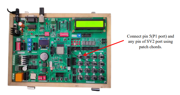
OTA (Over the air) programming
Aim: Turn ON and OFF an LED after Particular delay using OTA web server.
Description: To learn how to connect LED to digital pins of an ESP32 Microcontroller and program to blink an LED using OTA web server.
Hardware Requirement: ESP32 - Microcontroller development board.
Procedure:
1. When you install the ESP32 add-on for the Arduino IDE, it will automatically install the Arduino OTA library.
2. Go toFile > Examples >ArduinoOTA> OTAWebUpdater
3. Write the program, verify and Upload it.
3. The following code should load
#include <WiFi.h>
#include <WiFiClient.h>
#include <WebServer.h>
#include <ESPmDNS.h>
#include <Update.h>
const char* host = "esp32";
const char* ssid = "****"; // enter your WiFi SSID
const char* password = "*****"; // enter your WiFi Password
WebServer server(80); //WebServer initiated with port 80
/*
 * Login page
 */
const char* loginIndex =
"<form name="loginForm">""<table width="20%" bgcolor="A09F9F" align="center">"
"<tr>"
"<td colspan="2">" "<center><font size="4"><b>ESP32 Login
Page</b></font></center>""<br>""</td>""<br>" "<br>" "</tr>""<tr>"
"<td>Username:</td>"
"<td><input type="text" size="25" name="userid"><br></td>"
"</tr>" "<br>" "<br>"
"<tr>"
"<td>Password:</td>" "<td><input type="Password" size="25" name="pwd"><br></td>"
"<br>" "<br>" "</tr>"
"<tr>"
"<td><input type="submit" onclick="check(this.form)" value="Login"></td>" "</tr>"
"</table>"
"</form>"
"<script>""function check(form)" "{"
 "if(form.userid.value=='admin' && form.pwd.value=='admin')" //You can
assign your user ID Password here
 "{"
 "window.open('/serverIndex')"
 "}"
 "else"
 "{"
 " alert('Error Password or Username')/*displays error message*/"
 "}"
 "}"
"</script>";

/*
 * Server Index Page
 */
const char* serverIndex =
"<script src="https://ajax.googleapis.com/ajax/libs/jquery/3.2.1/jquery.min.js"></script>"
"<form method="POST" action="#" enctype="multipart/form-data" id="upload_form">"
 "<input type="file" name="update">"
 "<input type="submit" value="Update">"
 "</form>"
"<div id="prg">progress: 0%</div>"
"<script>"
 "$("form").submit(function(e){"
 "e.preventDefault();"
 "var form = $('#upload_form')[0];"
 "var data = new FormData(form);"
 " $.ajax({"
 "url: '/update',"
 "type: 'POST',"
 "data: data,"
 "contentType: false,"
 "processData:false,"
 "xhr: function() {"
 "var xhr = new window.XMLHttpRequest();"
 "xhr.upload.addEventListener('progress', function(evt) {"
 "if (evt.lengthComputable) {"
  "var per = evt.loaded / evt.total;"
 "$('#prg').html('progress: ' + Math.round(per*100) + '%');"
 "}"
 "}, false);"
 "return xhr;"
 "},"
 "success:function(d, s) {"
 "console.log('success!')"
"},"
"error: function (a, b, c) {"
"}"
"});"
"});"
"</script>";
/*
 * setup function
 */
void setup(void) {
/*****************/
// use this section to write your new code which needs to run once for every Reset.
pinMode(5,OUTPUT);
/**************/

 Serial.begin(115200);
 // Connect to WiFi network
 WiFi.begin(ssid, password);
 Serial.println("");
 // Wait for connection
 while (WiFi.status() != WL_CONNECTED) {
 delay(500);
 Serial.print(".");
 }
 Serial.println("");
 Serial.print("Connected to ");
 Serial.println(ssid);
 Serial.print("IP address: ");
 Serial.println(WiFi.localIP());
 /*use mdns for host name resolution*/
 if (!MDNS.begin(host)) { //http://esp32.local
 Serial.println("Error setting up MDNS responder!");
 while (1) {
 delay(1000);
 }
 }
 Serial.println("mDNS responder started");
 /*return index page which is stored in serverIndex */
 server.on("/", HTTP_GET, []() {
 server.sendHeader("Connection", "close");
 server.send(200, "text/html", loginIndex);
 });
 server.on("/serverIndex", HTTP_GET, []() {
 server.sendHeader("Connection", "close");
 server.send(200, "text/html", serverIndex);
 });
 /*handling uploading firmware file */
 server.on("/update", HTTP_POST, []() {
 server.sendHeader("Connection", "close");
 server.send(200, "text/plain", (Update.hasError()) ? "FAIL" : "OK");
 ESP.restart();
 }, []() {
 HTTPUpload& upload = server.upload();
 if (upload.status == UPLOAD_FILE_START) {
 Serial.printf("Update: %s\n", upload.filename.c_str());
 if (!Update.begin(UPDATE_SIZE_UNKNOWN)) { //start with max available size
 Update.printError(Serial);
 }
 } else if (upload.status == UPLOAD_FILE_WRITE) {
 /* flashing firmware to ESP*/
 if (Update.write(upload.buf, upload.currentSize) != upload.currentSize) {
 Update.printError(Serial);
 }
 } else if (upload.status == UPLOAD_FILE_END) {
 if (Update.end(true)) { //true to set the size to the current progress
 Serial.printf("Update Success: %u\nRebooting...\n", upload.totalSize);
 } else {
 Update.printError(Serial);
 }
 }
 });
 server.begin();
}
void loop(void) {
 server.handleClient();
 /*******************/
// use this section to write your new code which needs to run continuously.
 digitalWrite(5,HIGH);
 delay(1000);
 digitalWrite(5,LOW);
 delay(1000);
 /*******************/

 delay(10);
}
4. You should change the following lines on the code to include your own network
credentials
![]() const char* ssid = “ ” ;
const char* ssid = “ ” ;
![]() const char* password = “ ” ;
const char* password = “ ” ;
5. Upload the above code to ESP32 board. Enter proper network credentials.
6. Now select proper board and serial port.
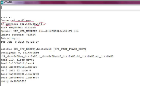
7. Once the code is uploaded, open serial monitor select baud rate 115200 and press enable button and then you will get ESP32 IP address.
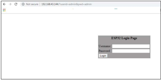
Password: admin
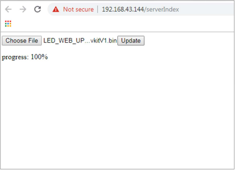
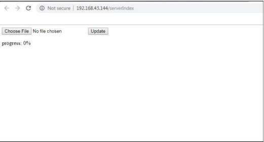
10. After entering the username and password a new tab should open on the /serverIndex URL. This page allows you to upload a new code to your ESP32. You should upload .bin files.
Preparing the sketch:
1. Write a simple program (Blinking of LED) using OTA web server and save it with the name LED_blink and complile it.
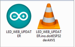
2. Once the uploading is done go to Sketch<Export compiled binary.
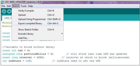
4. In this folder two files will be generated .ino and .bin.
5. You should upload the .bin file using OTA Web Server.
7. Select .bin file and click Update.
8. Code will be successfully uploaded.