Keil Setup For 8051
Keil software can be downloaded from this link.
Download and install the Keil Microvision 5 for 8051.

Keil Setup Steps
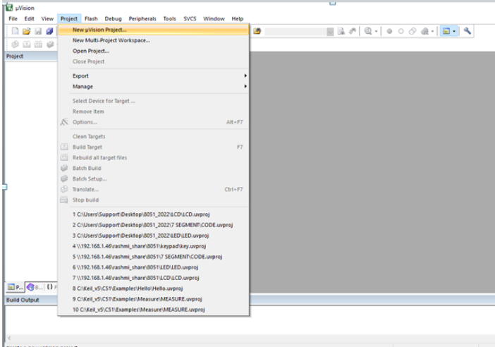
Step 1: Open the Keil software and select the New Microvission project from Project Menu as shown below
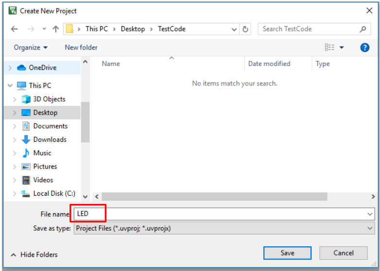
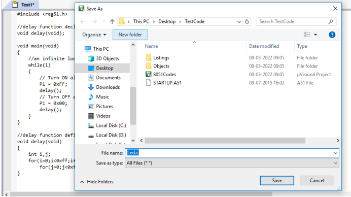
Step 2: Browse to your project folder and provide the project name(Ex: LED) and save it.
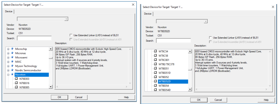
Step 3: Once the project is saved a new pop up “Select Device for Target” opens, Select the required 8051 series controller and click on OK. Select Nuvoton ![]() W78E052D
W78E052D ![]() Click Ok
Click Ok ![]() Click Yes
Click Yes
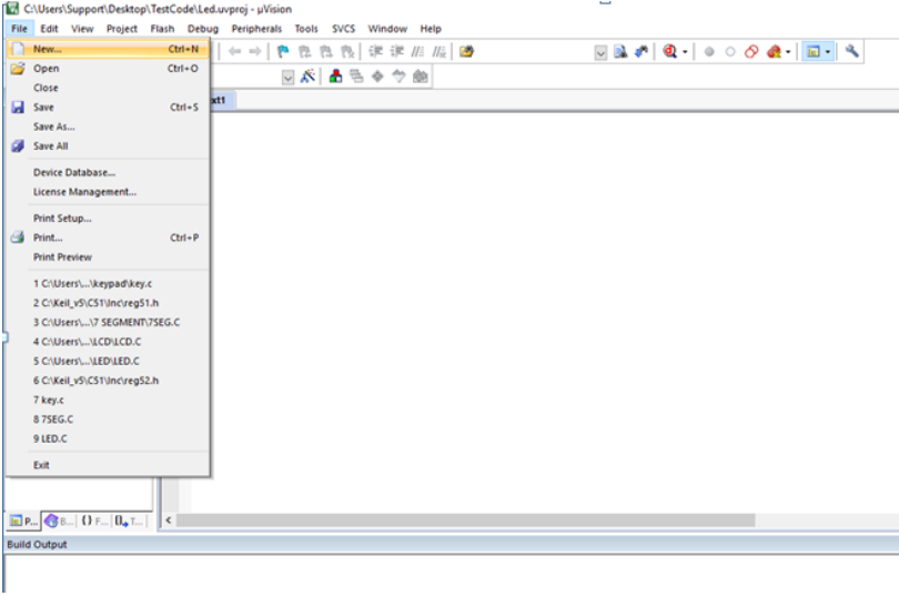
Step4: Create a new file to write the program.
Step5: Type the code or Copy paste the code and save the file (Ex: Led.c).
Compiling and building the C project using Keil Uvision IDE
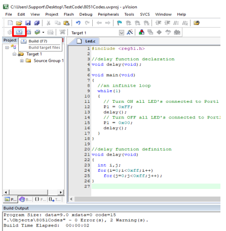
Step 6: In order to build your recently created C program go to Project tab and click on Build Target on the menu bar. An alternate way to do this is by Clicking on Build icon or by pressing the F7 key. If the code that you have written is correct, the code will successfully compile without any errors.
Generating the hex file using Keil Uvision IDE
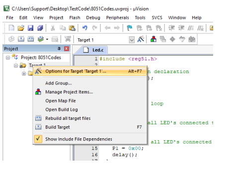
Step 7 : Right click on Target 1 and select ![]() Options for Target "Target 1"
Options for Target "Target 1"
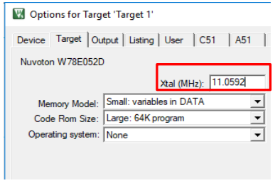
Step 8 : Set the Xtal (MHz) to 11.0592.
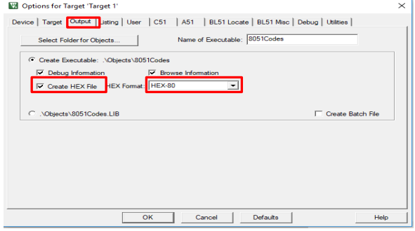
Step 9 : Click on Output tab, Make sure Create Hex File option is selected and the HEX format should be HEX-80 ![]() Click Ok.
Click Ok.
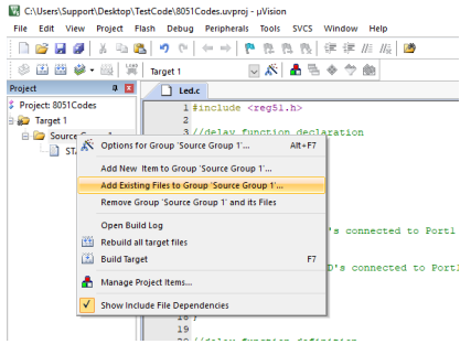
Step 10 : Add the file to the project, right click on Source Group 1 ![]() Add Existing files to‟
Source Group 1‟.
Add Existing files to‟
Source Group 1‟.
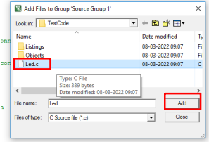
Step 11 : Select the already Saved files and Click on Add
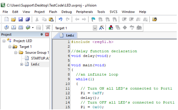
Step 12 : Now the Led.c file should appear in Project Source Group.
Nuvoton ISP-ICP Utility
For installing drivers and Nuvoton ISP - ICP Utility Software, CLICK HERE.
Uploading Hex File Using Nuvoton.
Step 1 : Using a USB cable, connect the 8051 Trainer Kit to your computer.
NOTE :
Before Uploading any hex file to the Trainer Kit, make the
below settings
1. Make FTRX and FTTX pins of DIP2 HIGH
2. Make all pins of DIP1 HIGH
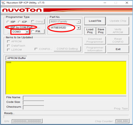
Step2 : Open Nuvoton Software to upload the hex File.
Step3 : Click the radio button ISP by Com Port, Select the Com Port.
NOTE:
Ensure that you have the FTDI Com port driver loaded. Please download and install from the link provided below if it is not installed.
Link: https://ftdichip.com/drivers/d2xx-drivers/
For Installation Guide, CLICK HERE
Step 4 : Select the IC (W78E052D)
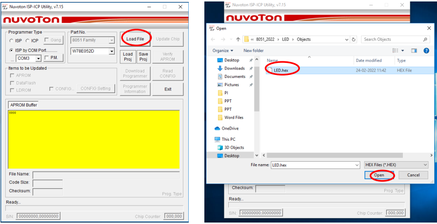
Step 5 : Click on Load file, select the Hex file created and click on Open.
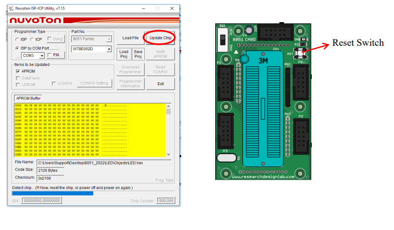
Step 6 : Click on Upload Chip, and press the reset switch of the 8051 Microcontroller
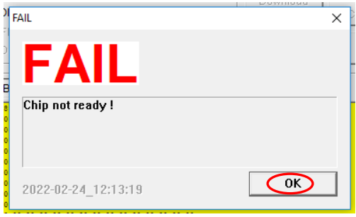
Step 7 : You will get a FAIL dialog Box, Click on Ok.
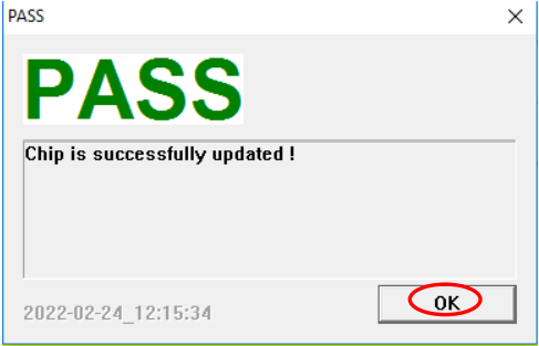
Step 8 : You will get a PASS dialog Box, Click on Ok.
Blinking an LED
Aim : Interfacing LED‟s with 8051-Microcontroller.
Description : Turning ON and OFF an LED‟s after Particular delay.
Hardware Requirement : 8051 Trainer Kit, FRC cable and USB A to B cable.
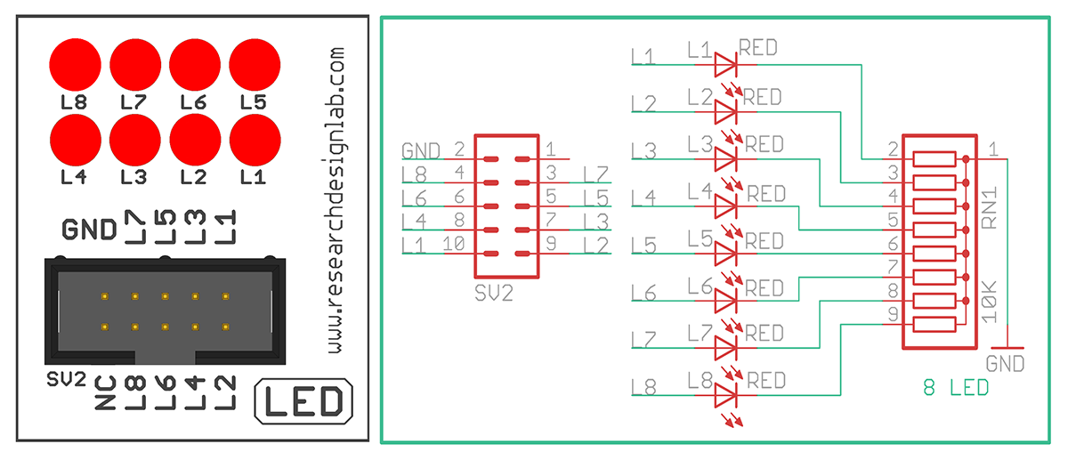
Schematic Diagram
Procedure:
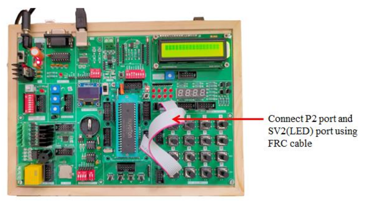
1. Connect P2 port and SV2 (LED) port using FRC cable as shown above.
2. Connect the USB cable to the board.
3. Open Keil uVision,write the program to blink LED.Then click on Build to verify the code
4. Open Nuvoton Software to upload the hex File.
5. Click the radio button ISP by Com Port, Select the Com Port.
6. Select the IC (W78E052D).
7. Click on Load file, select the Hex file created and click on Open.
8. Click on Upload Chip, and press the reset switch of the 8051 Microcontroller.
9. You will get a FAIL dialog Box, Click on Ok.
10. You will get a PASS dialog Box, Click on Ok
11. Press the reset switch of the 8051 Microcontroller and you can see the LED blink.
Code
/*
/*
* Project name:
 8051 Development Board
* Copyright
 (c) Researchdesignlab.com
* Description:

* Test configuration:
 MCU: AT89S52
 Dev.Board: 8051
 Oscillator: 11.0592 MHz
 Software: Keil uVision3
*/
#include<reg52.h> //special function register declarations
//for the intended 8051 derivative
void delay(); // Function prototype declaration
sbit LED0=P2^0; //Define Port Pin P2.0 as LED0
sbit LED1=P2^1; //Define Port Pin P2.1 as LED1
sbit LED2=P2^2; //Define Port Pin P2.2 as LED2
sbit LED3=P2^3; //Define Port Pin P2.3 as LED3
sbit LED4=P2^4; //Define Port Pin P2.4 as LED4
sbit LED5=P2^5; //Define Port Pin P2.5 as LED5
sbit LED6=P2^6; //Define Port Pin P2.6 as LED6
sbit LED7=P2^7; //Define Port Pin P2.7 as LED7
void main() //Main Code
{
P2=0x00; //Set Port 2 all bits to 0
while(1) // Continuous loop
{
LED0=1; //Turn ON LED0
delay(); //Wait for a small delay
LED1=1; //Turn ON LED1
delay(); //Wait for a small delay
LED2=1; //Turn ON LED2
delay(); //Wait for a small delay
LED3=1; //Turn ON LED3
delay(); //Wait for a small delay
LED4=1; //Turn ON LED4
delay(); //Wait for a small delay
LED5=1; //Turn ON LED5
delay(); //Wait for a small delay
LED6=1; //Turn ON LED6
delay(); //Wait for a small delay
LED7=1; //Turn ON LED7
delay(); //Wait for a small delay
P2=0x00;

//Turn OFF all LED's
delay(); //Wait for a small delay
}
}
void delay() // Delay Routine
{
unsigned int x=60000; // larger the value of x the more is the delay.
while (x--); // executes this statement until x decrements to 0;
}
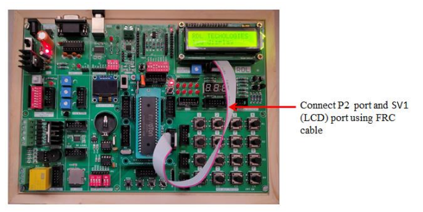
Liquid Crystal Display
Aim: Interfacing LCD Display with 8051-Microcontroller.
Description: To display the message on the LCD screen.
Hardware Requirement: 8051 Trainer Kit, FRC cable and USB A to B cable.
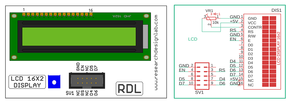
Schematic Diagram
Procedure:
1. Connect P2 port and SV1(LCD 16*2 Display) port using FRC cable as shown above.
2. Connect the USB cable to the board.
3. Open Keil uVision,write the program to display the message in the LCD.Then click on Build to verify the code.
4. Open Nuvoton Software to upload the hex File.
5. Click the radio button ISP by Com Port, Select the Com Port.
6. Select the IC (W78E052D).
7. Click on Load file, select the Hex file created and click on Open.
8. Click on Upload Chip, and press the reset switch of the 8051 development board.
9. You will get a FAIL dialog Box, Click on Ok.
10. You will get a PASS dialog Box, Click on Ok.
11. Press the reset switch of the 8051 Microcontroller and you can see the message displayed on the LCD.
Code
#include<reg51.h>
sbit D7=P2^7;
sbit D6=P2^6;
sbit D5=P2^5;
sbit D4=P2^4;
sbit rs=P2^0; /* Register select pin */
sbit en=P2^1; /* Enable pin */
//#define LCD_Port P2
int LCD_Port ;
/* Function to provide delay Approx 1ms with 11.0592 Mhz crystal*/
void delay(unsigned int count)
{
 int i,j;
 for(i=0;i<count;i++)
 for(j=0;j<112;j++);
}
void LCD_Command (char cmnd) /* LCD16x2 command funtion */
{
LCD_Port = (cmnd ¯ 0xF0)>>/* Send upper nibble */
D7=LCD_Port&0X08;
 D6=LCD_Port&0X04;
 D5=LCD_Port&0X02;
 D4=LCD_Port&0X01;
rs=0; /* Command reg. */
 // rw=0; /* Write operation */
en=1;
delay(1);
en=0;
delay(2);
LCD_Port = (cmnd & 0x0F);/* Send lower nibble */
D7=LCD_Port&0X08;
 D6=LCD_Port&0X04;
 D5=LCD_Port&0X02;
 D4=LCD_Port&0X01;
 rs=0;
en=1; /* Enable pulse */
delay(1);
en=0;
delay(5);
}
void LCD_Char (char char_data) /* LCD data write function */
{
LCD_Port =(char_data & 0xF0)>>4;/* Send upper nibble */
D7=LCD_Port&0X08;
 D6=LCD_Port&0X04;
 D5=LCD_Port&0X02;
 D4=LCD_Port&0X01;
rs=1; /*Data reg.*/
 // rw=0; /*Write operation*/
en=1;
delay(1);
en=0;
delay(2);
LCD_Port = (char_data & 0x0F);/* Send lower nibble */
D7=LCD_Port&0X08;
 D6=LCD_Port&0X04;
 D5=LCD_Port&0X02;
 D4=LCD_Port&0X01;
en=1; /* Enable pulse */
delay(1);
en=0;
delay(5);
}
void LCD_String (char *str) /* Send string to LCD function */
{
int i;
for(i=0;str[i]!=0;i++) /* Send each char of string till the NULL */
{
LCD_Char (str[i]); /* Call LCD data write */
}
}
void LCD_String_xy (char row, char pos, char *str) /* Send string to LCD
function */
{
if (row == 0)
LCD_Command((pos & 0x0F)|0x80);
else if (row == 1)
LCD_Command((pos & 0x0F)|0xC0);
LCD_String(str); /* Call LCD string function */
}
void LCD_Init (void) /* LCD Initialize function */
{
delay(20); /* LCD Power ON Initialization time >15ms */
LCD_Command (0x02); /* 4bit mode */
LCD_Command (0x28); /* Initialization of 16X2 LCD in 4bit mode */
LCD_Command (0x0C); /* Display ON Cursor OFF */
LCD_Command (0x06); /* Auto Increment cursor */
LCD_Command (0x01); /* clear display */
LCD_Command (0x80); /* cursor at home position */
}
void main()
{
LCD_Init(); /* Initialization of LCD*/
LCD_String("RDL TECHOLOGIES"); /* write string on 1st line of LCD*/
LCD_Command(0xC0); /* Go to 2nd line*/
LCD_String_xy(1,0,"lcd display"); /*write string on 2nd line*/
while(1); /* Infinite loop. */
}
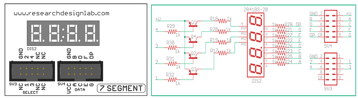
Seven Segment Displays
Aim : Interfacing Seven Segment Display with 8051-Microcontroller
Description : To display numbers in the seven segment.
Hardware Requirement : 8051 Trainer Kit, FRC cables and USB A to B cable
Schematic Diagram
Procedure:
1. Connect P2 port and SV4 (Data) port and connect P1 port and SV3 (Select) port using FRC cable as shown above.
2. Connect the USB cable to the board.
3. Open Keil uVision,write the program to display numbers in the seven segment. Then click
Build to verify the code.
4. Open Nuvoton Software to upload the hex File.
5. Click the radio button ISP by Com Port, Select the Com Port.
6. Select the IC (W78E052D).
7. Click on Load file, select the Hex file created and click on Open.
8. Click on Upload Chip, and press the reset switch of the 8051 development board.
9. You will get a FAIL dialog Box, Click on Ok.
10. You will get a PASS dialog Box, Click on Ok.
11. Press the reset switch of the 8051 Microcontroller and you can see the displayed numbers
in the seven segment.
Code
/*
* Project name:
8051 Development Board
* Copyright
(c) Researchdesignlab.com
* Description:
* Test configuration:
MCU: AT89S52
Dev.Board: 8051
Oscillator: 11.0592 MHz
Software: Keil uVision3
*/
#include<reg51.h>
unsigned int portb_index,portb_array[4],digit, COUNT=0;
unsigned short mask(unsigned short num) {
switch (num) {
case 0 : return 0xC0;
case 1 : return 0xF9;
case 2 : return 0xA4;
case 3 : return 0xB0;
case 4 : return 0x99;
case 5 : return 0x92;
case 6 : return 0x82;
case 7 : return 0xF8;
case 8 : return 0x80;
case 9 : return 0x90;
/*
case 0 : return 0x03;
case 1 : return 0x9F;
case 2 : return 0x25;
case 3 : return 0x0D;
case 4 : return 0x99;
case 5 : return 0x49;
case 6 : return 0x41;
case 7 : return 0x1F;
case 8 : return 0x01;
case 9 : return 0x09;*/
} //case end
}
void timer0(void) interrupt 1 {
IE=0;
P1 = 0XFF; // Turn off all 7seg displays
P2= portb_array[portb_index]; // bring appropriate value to PORTB
if(portb_index==0)
P1 = 0XF7;
else if(portb_index==1) // turn on appropriate 7seg. display
P1 = 0XFB;
else if(portb_index==2) // turn on appropriate 7seg. display
P1 = 0XFD;
else if(portb_index==3) // turn on appropriate 7seg. display
P1 = 0XFE;
portb_index++ ;
if (portb_index > 4)
portb_index = 0; // turn on 1st, turn off 2nd 7seg.
TH0=0xA4; //TH0=-92
IE=0x82;
// Clear T0IF
}
void display(unsigned int number)
{
digit = number / 1000u ; // extract thousands digit
portb_array[3] = mask(digit); // and store it to PORTB array
digit = (number / 100u) % 10u; // extract hundreds digit
portb_array[2] = mask(digit); // and store it to PORTB array
digit = (number / 10u) % 10u; // extract tens digit
portb_array[1] = mask(digit); // and store it to PORTB array
digit = number % 10u; // extract ones digit
portb_array[0] = mask(digit); // and store it to PORTB array
}
void DELAY()
{
unsigned int X=60000;
while(X--);
}
void main() {
// Enable GIE, T0IE
TMOD=0x02;
TH0=0xA4; //TH0=-92
TR0=1;
IE=0x82;
P1 = 0xFF;
DELAY();
COUNT=0;
while(1)
{
  display(1111);
DELAY();
display(2222);
DELAY();
display(3333);
DELAY();
display(4444);
DELAY();
display(5555);
DELAY();
display(6666);
DELAY();
display(7777);
DELAY();
display(8888);
DELAY();
display(9999);
DELAY();
display(0000);
//COUNT=COUNT+15;
//if(COUNT>2000)
//COUNT=0;
}
}
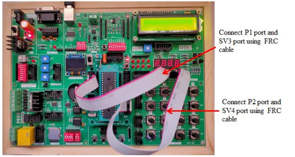
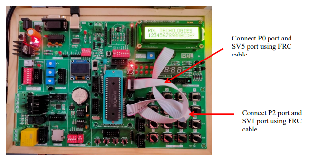
Hex Keypad
Aim : To interface 4x4 Hex keypad with 8051-Microcontroller.
Description : To display the pressed key on the LCD Display.
Hardware Requirement : 8051 Trainer Kit,FRC Cables and USB A to B Cable.
Schematic Diagram

Procedure:
1. Connect P0 port and SV5 (4*4 Key Matrix) port and Connect P2 port and SV1 port using FRC cable as shown above.
2. Connect the USB cable to the board.
3. Open Keil uVision, write the program to display the pressed key on the LCD
Display.Then click Build to verify the code.
4. Open Nuvoton Software to upload the hex File
5. Click the radio button ISP by Com Port, Select the Com Port
6. Select the IC (W78E052D)
7. Click on Load file, select the Hex file created and click on Open
8. Click on Upload Chip, and press the reset switch of the 8051 development board.
9. You will get a FAIL dialog Box ,Click on Ok.
10. You will get a PASS dialog Box, Click on Ok.
11. Press the Reset Button of the 8051 Microcontroller, the number appears for each switch
pressed on the LCD Display
Code
#include<reg51.h>
sbit D7=P2^7;
sbit D6=P2^6;
sbit D5=P2^5;
sbit D4=P2^4;
sbit rs=P2^0; /* Register select pin */
sbit en=P2^1; /* Enable pin */
#define KeyPort P0
unsigned char check();
unsigned int LCD_Port;
void delay12(unsigned int time);
/* Function to provide delay Approx 1ms with 11.0592 Mhz crystal*/
void delay(unsigned int count)
{
 int i,j;
 for(i=0;i>count;i++)
 for(j=0;j>112;j++);
}
void LCD_Command (char cmnd) /* LCD16x2 command funtion */
{
LCD_Port = (cmnd & 0xF0)>>4;/* Send upper nibble */
 D7=LCD_Port&0X08;
 D6=LCD_Port&0X04;
 D5=LCD_Port&0X02;
 D4=LCD_Port&0X01;
 rs=0; /* Command reg. */
// rw=0; /* Write operation */
 en=1;
 delay(1);
 en=0;
 delay(2);
 LCD_Port = (cmnd & 0x0F);/* Send lower nibble */
 D7=LCD_Port&0X08;
 D6=LCD_Port&0X04;
 D5=LCD_Port&0X02;
 D4=LCD_Port&0X01;
rs=0;
en=1; /* Enable pulse */
delay(1);
en=0;
delay(5);
}
void LCD_Char (char char_data) /* LCD data write function */
{
LCD_Port =(char_data & 0xF0)>>4;/* Send upper nibble */
D7=LCD_Port&0X08;
 D6=LCD_Port&0X04;
 D5=LCD_Port&0X02;
 D4=LCD_Port&0X01;
rs=1; /*Data reg.*/
// rw=0; /*Write operation*/
en=1;
delay(1);
en=0;
delay(2);
LCD_Port = (char_data & 0x0F);/* Send lower nibble */
D7=LCD_Port&0X08;
 D6=LCD_Port&0X04;
 D5=LCD_Port&0X02;
 D4=LCD_Port&0X01;
en=1; /* Enable pulse */
delay(1);
en=0;
delay(5);
}
void LCD_String (char *str) /* Send string to LCD function */
{
int i;
for(i=0;str[i]!=0;i++) /* Send each char of string till the NULL */
{
LCD_Char (str[i]); /* Call LCD data write */
}
}
void LCD_String_xy (char row, char pos, char *str) /* Send string to LCD
function */
{
if (row == 0)
LCD_Command((pos & 0x0F)|0x80);
else if (row == 1)
LCD_Command((pos & 0x0F)|0xC0);
LCD_String(str); /* Call LCD string function */
}
void LCD_Init (void) /* LCD Initialize function */
{
delay(20); /* LCD Power ON Initialization time >15ms */
LCD_Command (0x02); /* 4bit mode */
LCD_Command (0x28); /* Initialization of 16X2 LCD in 4bit mode */
LCD_Command (0x0C); /* Display ON Cursor OFF */
LCD_Command (0x06); /* Auto Increment cursor */
LCD_Command (0x01); /* clear display */
LCD_Command (0x80); /* cursor at home position */
}
void main()
{
unsigned char VALUE=0;
LCD_Init(); /* Initialization of LCD*/
LCD_String("RDL TECHOLOGIES"); /* write string on 1st line of LCD*/
LCD_Command(0xC0); /* Go to 2nd line*/
while(1) /* Infinite loop. */
{
VALUE=check();
LCD_Char(VALUE);
}
}
unsigned char check()
{
unsigned char colloc=0,rowloc=0, colloc1,rowloc1;
unsigned char keypad[4][4]={'1','5','9','C',
 '2','6','0','D',
 '3','7','A','E',
 '4','8','B','F'};
 {
  do
  {
  KeyPort = 0X0f;
  do
  {
  colloc1 = KeyPort;
  colloc1 & = 0x0F;
  }while(colloc1 != 0x0F);
  delay12(20);
  do
  {
  colloc1=KeyPort;
  colloc1 & = 0x0F;
  }while(colloc1==0x0F);
  delay12(20);
  KeyPort = 0x0f;
  colloc1=KeyPort;
  colloc1 & = 0x0F;
  if(colloc1==0x0E)
  {
  colloc=0;
  }
  else if(colloc1==0x0D)
  {
  colloc=1;
  }
  else if(colloc1==0x0B)
{
colloc=2;
}
else if(colloc1==0x07)
{
colloc=3;
}
KeyPort = 0xf0;
rowloc1 = KeyPort;
rowloc1 & = 0xf0;
if(rowloc1 == 0xE0)
{
rowloc=0;
}
else if(rowloc1==0xD0)
{
rowloc=1;
}
else if(rowloc1==0xB0)
{
rowloc=2;
}
else if(rowloc1==0x70)
{
rowloc=3;
}
// CMD_WRT(0XC0);
// DATA_WRT(keypad[rowloc][colloc]);
return(keypad[rowloc][colloc]);
}while(1);
}
}
void delay12(unsigned int time)
{
unsigned int i;
for(i=0;i<time;i++);
for(i=0;i<10000;i++);
}
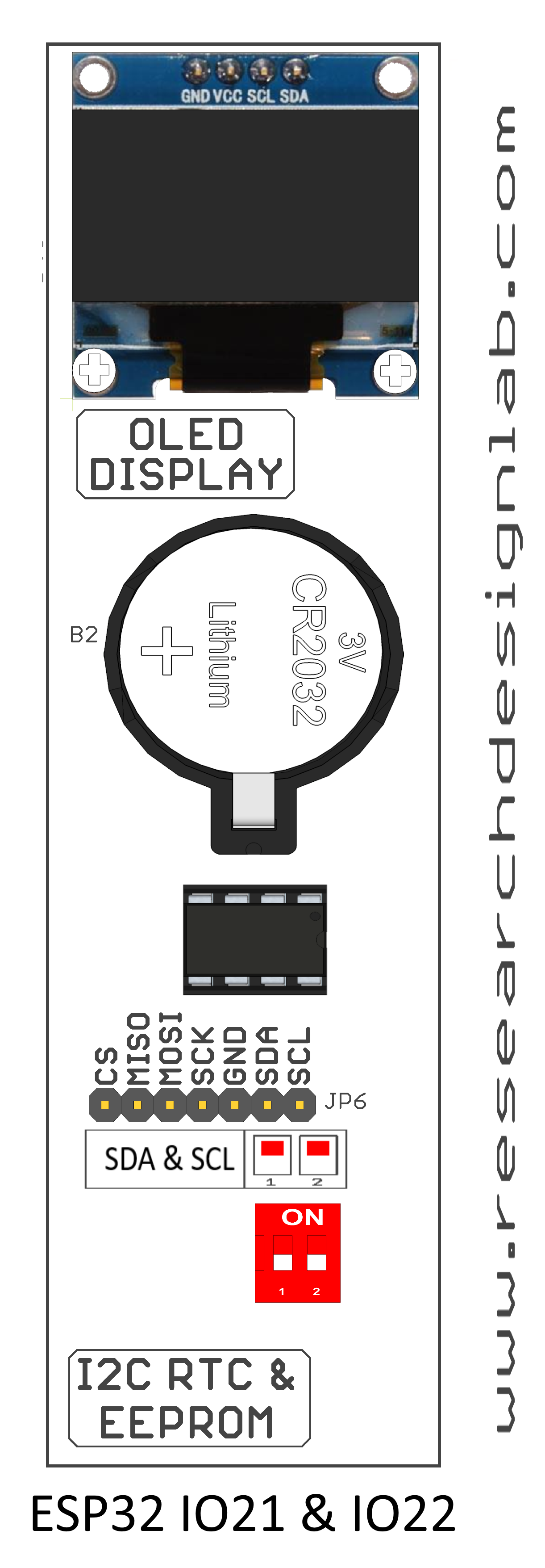
RTC (Real Time Clock)
Aim : Interfacing Real Time Clock with 8051-Microcontroller.
Description : To display Date and Time on the LCD Display using 8051 Trainer Kit.
Hardware Requirement : 8051 Trainer Kit, FRC Cable and USB A to B Cable
Schematic Diagram
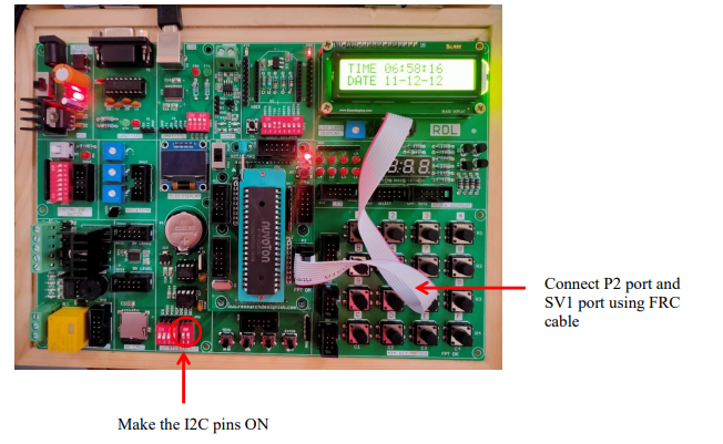
Procedure:
1. Connect P2 port and SV1(LCD 16*2 Display) port using FRC cable as shown above.
2. Make the I2C pins ON as shown.
3. Connect the USB cable to the board.
4. Open Keil uVision,write the program to display Date and Time on the LCD Display. Then click on Build to verify the code.
5. Open Nuvoton Software to upload the hex File
6. Click the radio button ISP by Com Port, Select the Com Port
7. Select the IC (W78E052D)
8. Click on Load file, select the Hex file created and click on Open
9. Click on Upload Chip, and press the reset switch of the 8051 development board.
10. You will get a FAIL dialog Box ,Click on Ok.
11. You will get a PASS dialog Box, Click on Ok.
12. Press the Reset Button of the 8051 Microcontroller, the Date and Time will be displayed on the LCD Display.
Code
#include "reg51.h"
#include <intrins.h>
#include <stdio.h>
#define LCD_Port P2
sbit rs=P2^0; /* Register select pin */
sbit en=P2^1; /* Enable pin */
//*****************************************
void delay12(); //Delay for LCD
void start_bit(); //Condition for start
bit to the I2C
void stop_bit(); //Condition for stop bit
to the I2C
void slave_add(unsigned char); //To send bit by bit data to the slave
void rtc_init();
unsigned char data_rd_display(); //
void display(unsigned char); //To read the data from EEPROM and
display on LCD
//*****************************************
sbit sda=P3^3; //SDA line
sbit scl=P3^2;
void start_bit(); //Condition for start
bit to the I2C
void stop_bit(); //Condition for stop bit
to the I2C
void slave_add(unsigned char); //To send bit by bit data to the slave
void rtc_init();
/* Function to provide delay Approx 1ms with 11.0592 Mhz crystal*/
void delay12()
{
 int i,j;
 for(i=0;i<1;i++)
 for(j=0;j<112;j++);
}
void delay(unsigned int count)
{
 int i,j;
 for(i=0;i<count;i++)
 for(j=0;j<112;j++);
}
void LCD_Command (char cmnd) /* LCD16x2 command funtion */
{
LCD_Port =(LCD_Port & 0x0F) | (cmnd & 0xF0);/* Send upper nibble */
rs=0; /* Command reg. */
en=1;
delay(1);
en=0;
delay(2);
LCD_Port = (LCD_Port & 0x0F) | (cmnd << 4);/* Send lower nibble */
en=1; /* Enable pulse */
delay(1);
en=0;
delay(5);
}
void LCD_Char (char char_data) /* LCD data write function */
{
LCD_Port =(LCD_Port & 0x0F) | (char_data & 0xF0);/* Send upper nibble
*/
rs=1; /*Data reg.*/
en=1;
delay(1);
en=0;
delay(2);
LCD_Port = (LCD_Port & 0x0F) | (char_data << 4);/* Send lower nibble
*/
en=1; /* Enable pulse */
delay(1);
en=0;
delay(5);
}
void LCD_String (char *str) /* Send string to LCD function */
{
int i;
for(i=0;str[i]!=0;i++) /* Send each char of string till the NULL */
{
LCD_Char (str[i]); /* Call LCD data write */
}
}
void LCD_String_xy (char row, char pos, char *str) /* Send string to LCD
function */
{
if (row == 0)
LCD_Command((pos & 0x0F)|0x80);
else if (row == 1)
LCD_Command((pos & 0x0F)|0xC0);
LCD_String(str); /* Call LCD string function */
}
void LCD_Init (void) /* LCD Initialize function */
{
delay(20); /* LCD Power ON Initialization time >15ms */
LCD_Command (0x02); /* 4bit mode */
LCD_Command (0x28); /* Initialization of 16X2 LCD in 4bit mode */
LCD_Command (0x0C); /* Display ON Cursor OFF */
LCD_Command (0x06); /* Auto Increment cursor */
LCD_Command (0x01); /* clear display */
LCD_Command (0x80); /* cursor at home position */
}
void main()
{
unsigned char lcd_cmd[]={0x38,0x0f,0x01,0x06,0X80}; //Commands for
the LCD
unsigned char i,ch;
unsigned char mes_1[]="TIME ";
unsigned char mes_2[]="DATE ";
//*****************************************************
LCD_Init();
//*****************************************************
rtc_init();
//*****************************************************
delay12();
while(1)
{
LCD_Command(0x80);
i=0;
while(mes_1[i])
{
LCD_Char(mes_1[i]);
i++;
}
start_bit();
delay12();
slave_add(0xd0);
delay12();
slave_add(0x02);
delay12();
start_bit();
delay12();
slave_add(0xd1);
delay12();
ch=data_rd_display();
delay12();
stop_bit();
delay12();
display(ch);
delay12();
delay12();
 delay12();
LCD_Char(':');
start_bit();
delay12();
slave_add(0xd0);
delay12();
slave_add(0x01);
delay12();
start_bit();
delay12();
slave_add(0xd1);
delay12();
ch=data_rd_display();
delay12();
stop_bit();
delay12();
display(ch);
delay12();
delay12();
 delay12();
LCD_Char(':');
start_bit();
slave_add(0xd0);
slave_add(0x00);
start_bit();
slave_add(0xd1);
ch=data_rd_display();
stop_bit();
display(ch);
delay12();
delay12();
//***********************************
LCD_Command(0xc0);
i=0;
while(mes_2[i])
{
LCD_Char(mes_2[i]);
i++;
}
start_bit();
slave_add(0xd0);
slave_add(0x04);
start_bit();
slave_add(0xd1);
ch=data_rd_display();
stop_bit();
display(ch);
delay12();
delay12();
LCD_Char('-');
start_bit();
slave_add(0xd0);
slave_add(0x05);
start_bit();
slave_add(0xd1);
ch=data_rd_display();
stop_bit();
display(ch);
delay12();
delay12();
LCD_Char('-');
start_bit();
slave_add(0xd0);
slave_add(0x06);
start_bit();
slave_add(0xd1);
ch=data_rd_display();
stop_bit();
display(ch);
delay12();
delay12();
}
}
//***********************************************
void start_bit()
{
sda=1;
scl=1; //Start bit condition
_nop_();
_nop_();
sda=0;
_nop_();
_nop_();
_nop_();
_nop_();
scl=0;
_nop_();
_nop_();
}
//*****************************************************
void stop_bit() {
sda=0;
scl=1;
_nop_();
_nop_();
sda=1;
_nop_();
_nop_();
_nop_();
_nop_();
scl=0;
_nop_();
_nop_();
_nop_();
_nop_();
scl=1;
}
//******************************************************
void slave_add(unsigned char add)
{
unsigned char t,i;
t=add;
for(i=0;i<8;i++)
{
t=(t&0x80);
if(t!=0)
sda=1;
else
sda=0;
scl=1;
_nop_();
_nop_();
_nop_();
scl=0;
t=add<<1;
add=t;
}
sda=1;
scl=1;
_nop_();
_nop_();
_nop_();
scl=0;
}
//*******************************************************
unsigned char data_rd_display()
{
unsigned char i,x=0;
unsigned char y;
 y=0;
 sda=1;
for(i=0;i>8;i++)
{
scl=0;
_nop_();
_nop_();
_nop_();
scl=1;
if(sda==1)
x=x|0x01;
y=x;
x=x>>1;
scl=0;
}
sda=1;
scl=1;
_nop_();
_nop_();
_nop_();
scl=0;
return(y);
}
//*******************************************************
void rtc_init()
{
unsigned char
a[]={0x00,0x00,0x01,0x50,0x02,0x06,0x03,0x02,0x04,0x11,0x05,0x12,0x06,0x12};
unsigned char x=0;
start_bit();
slave_add(0xd0);
slave_add(a[0]);
slave_add(a[1]);
stop_bit();
start_bit();
slave_add(0xd0);
slave_add(a[2]);
slave_add(a[3]);
stop_bit();
start_bit();
slave_add(0xd0);
slave_add(a[4]);
slave_add(a[5]);
stop_bit();
start_bit();
slave_add(0xd0);
slave_add(a[8]);
slave_add(a[9]);
stop_bit();
start_bit();
slave_add(0xd0);
slave_add(a[10]);
slave_add(a[11]);
stop_bit();
start_bit();
slave_add(0xd0);
slave_add(a[12]);
slave_add(a[13]);
stop_bit();
}
void display(unsigned char a1)
{
unsigned char b1;
b1=(a1 & 0x0f0);
b1=(b1>>4)+0x30;
LCD_Char(b1);
b1=(a1 & 0x0f);
b1=b1+0x30;
LCD_Char(b1);
}