MCU
- ESP32-D0WD-V3 embedded, Xtensa® dual-core 32-bit LX6 microprocessor, up to 240 MHz.
- 448 KB ROM for booting and core functions.
- 520 KB SRAM for data and instructions.
- 16 KB SRAM in RTC.
- 4 MB SPI flash.
Wi-Fi
- 802.11b/g/n.
- Bit rate: 802.11n up to 150 Mbps.
- A-MPDU and A-MSDU aggregation.
- 0.4 µs guard interval support.
- Center frequency range of operating channel: 2412 ~ 2484 MH.
Bluetooth® / BLE
- Bluetooth V4.2 BR/EDR and Bluetooth LE specification.
- Class-1, class-2 and class-3 transmitter.
- AFH.
- CVSD and SBC.
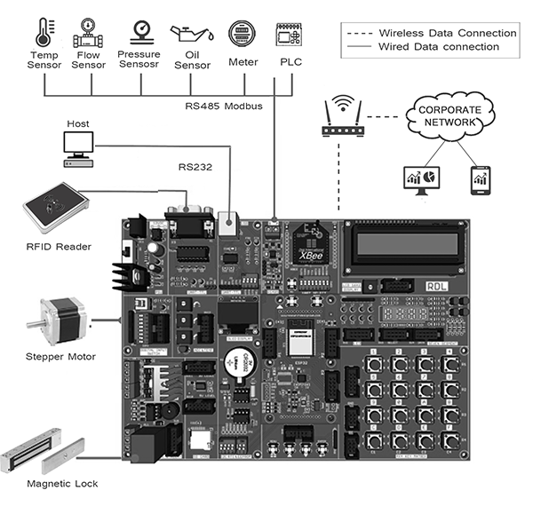
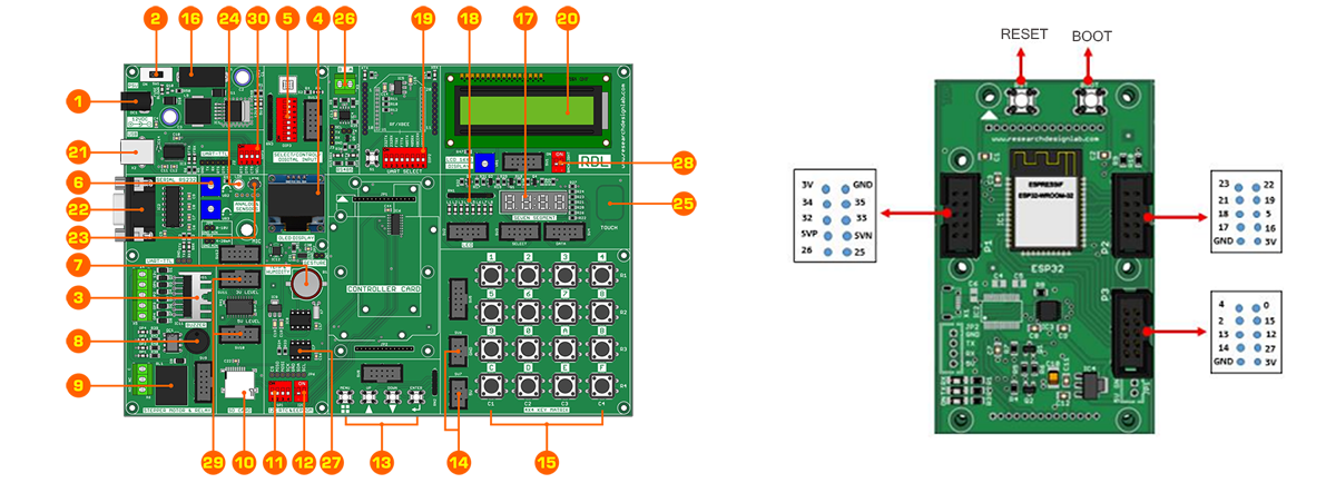
Hardware Interfaces
SD card, UART, SPI, SDIO, I2C, LED PWM, Motor PWM, I2S, IR, pulse counter, GPIO, capacitive touch sensor, ADC, DAC, Two-Wire Automotive Interface
Communication Interfaces
RS232, RS485 ( Modbus RTU ), USB, SPI, I2C.
On Board Peripheral
OLED Display , 16x2 LCD Display,Seven Segment Display, 8x LED, 4x4 Hex Keypad, 1x4 Menu Keypad, Xbee Adapter, 3.3 to 5v Level Converter, SD CARD Interface, RTC & EEPROM, DC Motor / Stepper Motor Driver, Relay, Buzzer,1xTemperature Sensor, 3x Analog Test POT, 8x Selection DIP Switch.