RDL740

PIC Development Board

PIC Development Board

PIC Development Board

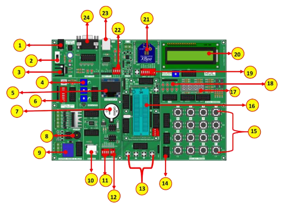
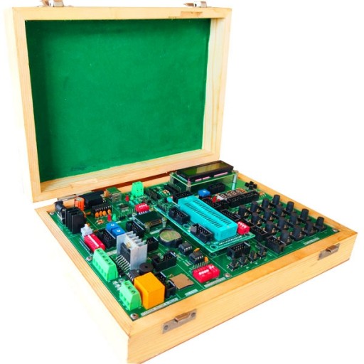
PIC essential development features a plug-and-play design that makes it easy for connections and helps Students, hobbyists, enthusiasts, and professionals to focus more on Program / application development. PIC Development Board Trainer kit equipped with on board IO’s, communication interfaces & peripherals. It is really easy to design, experiment with, and test circuits without soldering. It’sused in many educational institutions and R&D LAB across the world.
Features

  •  Plug & Play Interface Connectivity.
  •  Professional EMI/RFI Complaint PCB Layout Design.
  •  Modular Block design makes Easy access & quick Prototyping.
  •  FRC connectivity features minimize the connection Error.
  •  High Quality Grade PCB with wooden Enclosure.
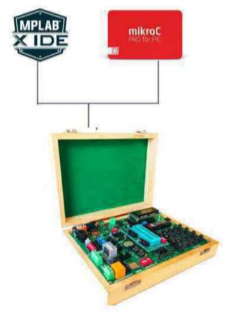
  •  On board Programming.
  •  8 interfacing LED’s.
  •  1*4 Menu keypad.
  •  4*4 Matrix Keypad.
  •  RS232, RS485, USB communication port.
  •  7 Segment Multiplexed Display.
  •  16*2 LCD & OLED Display
  •  8 bit 4 port IO.
  •  On Board WiFi / Bluetooth Connectivity.
  •  3.3 to 5V Level Converter.
  •  Power Supply 3.3V and 5V.
  •  SD CARD Interface.
  •  RTC & EEPROM Interface.
  •  DC Motor/ Stepper Motor Driver.
  •  Relay, Buzzer.
  •  1xTemperature Sensor.
  •  3x Analog Test POT.

Note

Optional OLED & SDCARD modules are provided on this board, Hobbyists/developers can make use of this module with their previous knowledge or open-source community support and we do not have the support for the optional module.

MCU

  • Only 35 single-word instructions to learn.
  • All single-cycle instructions except for program branches, which are two-cycle.
  • Operating speed: DC – 20 MHz clock input DC – 200 ns instruction cycle.
  • Up to 8K x 14 words of Flash Program Memory, Up to 368 x 8 bytes of Data Memory (RAM), Up to 256 x 8 bytes of EEPROM Data Memory.
  • Pinout compatible to other 28-pin or 40/44- pin PIC16CXXX and PIC16FXXX microcontrollers.

Analog Features

  • 10-bit, up to 8-channel Analog-to- Digital Converter(A/D).

Peripheral Features

  • Timer0: 8-bit timer/counter with 8-bit prescaler.
  • Timer1: 16-bit timer/counter with prescaler.
  • Timer2: 8-bit timer/counter with 8-bit period register,prescaler and postscaler.
  • Two Capture, Compare, PWMmodules.
  • Synchronous Serial Port (SSP) with SPI™ (Mastermode) and I2C™ (Master/Slave).
  • Universal Synchronous Asynchronous Receiver Transmitter (USART/SCI) with 9-bit address detection.
  • Parallel Slave Port (PSP) – 8 bits wide with external RD,WR and CS controls (40/44-pin only).

Scope of Learning Experiments:

  • LED blinking.
  • 8 bit LED Left shift, Right shift and counting operation.
  • Keypad Interrupt Interface.
  • 16*2 LCD interface.
  • Matrix Keypad Interface.
  • ADC & DAC interface.
  • Traffic Light Signal Interface.
  • 8 bit DIP switch interface.
  • 7 Segment interface.
  • L298 Driver for DC Motor and Stepper motor interface.
  • Elevator Interface.
  • Buzzer, Relay interface.
  • RS485, RS232 serial communication.
  • PWM Interface.
  • UART Operation.
  • RTC DS1307I2C protocol interface.
  • AT24C04 EEPROM I2C protocol interface.
  • RF/WiFiCommunication.
  • SPI protocol interface.
  • Temperature Sensor Interface.

Supported IC:

PIC16F74, PIC16F77, PIC16F747, PIC16F777, PIC16F871, PIC16F874, PIC16F877, PIC16F877A, PIC16F887, PIC18F452, PIC18F458, PIC18F4220, PIC18F4320, PIC18F4431, PIC18F4331, PIC18F4520, PIC18F4420, PIC18F4550, PIC18F4455, PIC18F4580, PIC18F4480, PIC18F4585, PIC18F4680, PIC18F4620, PIC18F45J10, PIC18F44J10, PIC18F44J, PIC18F43K20, PIC18F44K20, PIC18F46K20.

Package Contains:

  • Development Board with Wooden Enclosure
  • USB Cable.
  • 12V 2A Adapter.
  • FRC Cable