PIC Board Narration

2. Power ON Switch
3. Heat Sink
4. ADC (Variable Resistor POT)
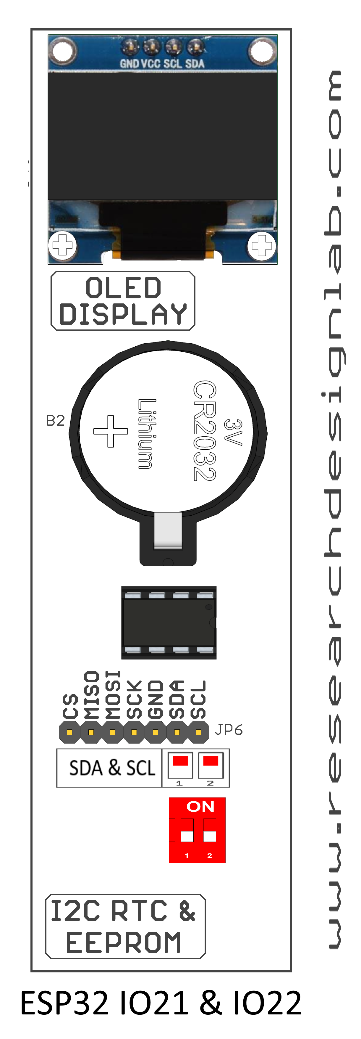
5. OLED Display
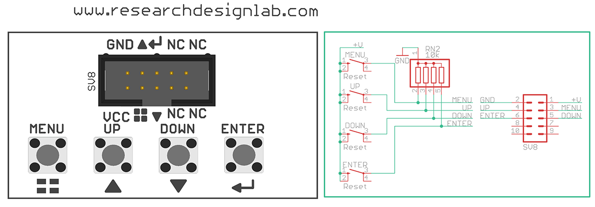
6. Digital Input Switch
7. RTC Battery
8. Buzzer
9. Relay
10. SD Card Holder
11. Jumper Settings for I2C RTC
12. Jumper Settings for EEPROM
14. RDL Bus FRC Connector
15. Keypad Matrix
16. PIC Controller
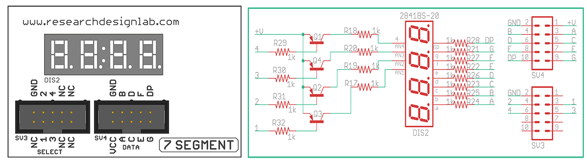
17. 7 Segment Display
18. 2*4 LED's
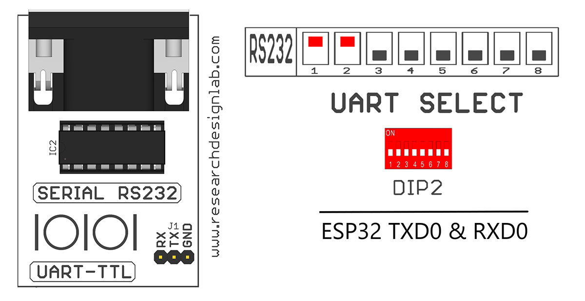
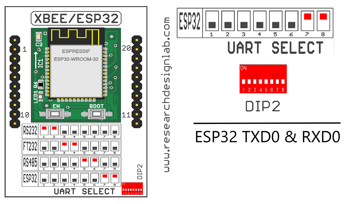
19. Jumper Settings for UART Selection Pin
20. 16*2 LCD Display
21. WiFi Module
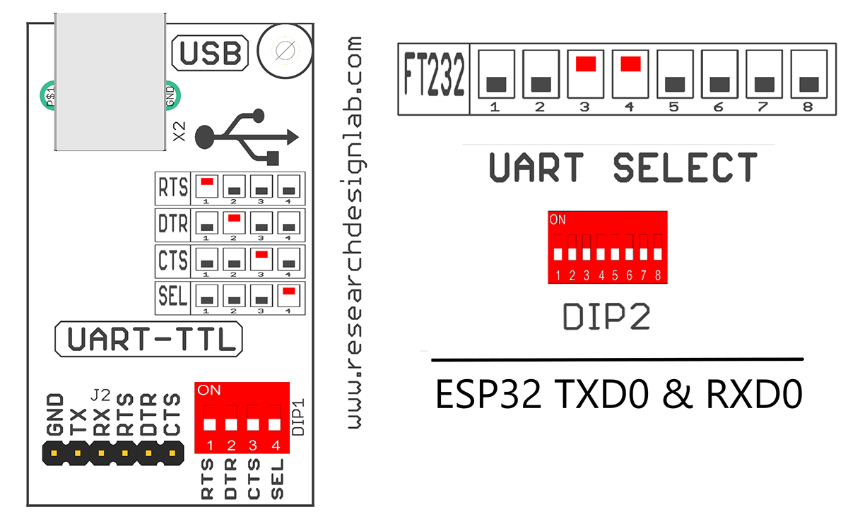
22. Jumper Settings for UART TTL
23. USB Port
24. DB-9 Serial Female Connector

Application:
- Light sensing & controlling devices
- Temperature sensing and controlling devices
- Fire detection & safety devices
- Industrial instrumentation devices
- Application of microcontroller in Industrial Control Devices
- Process Control Devices
- Industrial instrumentation devices
- IoT Applications
- Automation Applications
Package Includes:
- Development Board with Wooden Enclosure
- USB Cable
- 12V 2A Adapter.
- FRC Cable
MikroC PRO for PIC
Download and install the MikroC PRO for PIC,CLICK HERE.
Create a New Folder (Ex:PIC_RTC)

Step1: Open the MikroC PRO software and once the MikroC compiler started, you will see a screen as shown below.

Step2: Create a New Project from the menu bar by going to Project >> New Project.

Step3: “New Project Wizard” window opens. Select a Standard project and click Next.

Step4: Type Project Name (Ex:RTC), Browse the Folder which you have already created to save your project(Ex:PIC_RTC), PIC Microcontroller device is P18F877A and Device clock (set it to 20MHz). Then click Next.

Step5: Click on Finish.

Step6: A window shown below appears. Write your program.

Step7: Click on System Libraries and select the required libraries/all the libraries from the list and click on rebuild libraries.

Step8: We have given RTC Example Code below. Click on Save and give the file name (Ex:RTC) and save it in the Project folder which was created before (Ex:PIC_RTC).


Compile Code with MikroC
Step9: After Saving the code, Click on Build from Menu bar. If everything is right it will display a message of finish successfully in the below window.

Step10: After that go to the project folder(Ex:PIC_RTC) where you saved your project and locate the hex file. Because we will use this hex file to program Pic Microcontroller.

Installation of PicKit2
For download & installing Pickit2 Software,CLICK HERE.
Uploading Hex File Using Pickit2
NOTE:
Before Uploading any hex file to the Trainer Kit, make the below settings
1. Make FTRX and FTTX pins of DIP2 HIGH
2. Make all pins of DIP1 HIGH
For Pickit2 User Guide,CLICK HERE (Refer till Page 16 to load the hex file to the development Board).
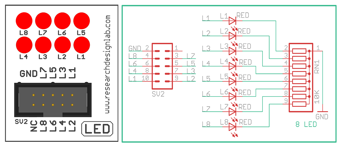
Blinking an LED
Aim: Interfacing LED’s with PIC-Microcontroller.
Description: Turning ON and OFF an LED’s after Particular delay.
Hardware Requirement: PIC Trainer Kit, Pickit2 Programmer, FRC cables, USB A to B cable and 12V 2A Adapter.
Schematic Diagram

Procedure:
1. Connect ISP port of the Trainer Kit and ISP Port of the Pickit2 Programmer using FRC cable.
2. Connect PB port and SV2 (LED) port using FRC cable as shown above.
3. Connect the USB cable to the programmer and connect the Power Adapter to the PIC Trainer Kit.
4.Open MikroC Pro,write the program.Then click on Build to verify the code.
5. Click the radio button ISP by Com Port, Select the Com Port.
6. Open Pickit2 Software to upload the hex File (Follow the steps given in the Pickit2 User Guide).
7. Once the hex file is written successfully,Press the reset switch of the PIC Microcontroller and you can see the LED blink.
Code
/*
/*
* Project name:
PIC Development Board LED and Keypad code
* Copyright
(c) Researchdesignlab.com
* Test configuration:
MCU: PIC16F877A
Dev.Board: PIC
Oscillator: 20.0 MHz
Software: mikroC PRO for PIC v 4.6
Developer: DD
*/
sbit LED1 at RB0_bit; //defining PortB Pin B0 as LED1
sbit LED2 at RB1_bit; //defining PortB Pin B1 as LED2
sbit LED3 at RB4_bit; //defining PortB Pin B4 as LED3
sbit LED4 at RB5_bit; //defining PortB Pin B5 as LED4
void main()
{
TRISB=0x00; //defining PORTB as output port
PORTB= 0XFF;
Delay_ms(1000);
PORTB= 0X00;
Delay_ms(1000);
while(1)
{
PORTB=0xFF; //binary equivalent value:00000000
Delay_ms(1000);
PORTB=0x00; //binary equivalent value:11111111
Delay_ms(1000);
}
}
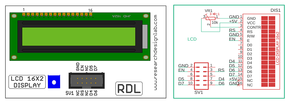
Liquid Crystal Display
Aim:Interfacing LCD Display with PIC-Microcontroller.
Description:To display the message on the LCD screen.
Hardware Requirement: PIC Trainer Kit, Pikit2 Programmer, FRC cables,USB A to B cable and 12V 2A Power Adapter.
Schematic Diagram

Procedure:
1. Connect ISP port of the Trainer Kit and ISP Port of the Pickit2 Programmer using FRC cable.
2. Connect PB port and SV1 (LCD 16*2 Display) port using FRC cable as shown above.
3. Connect the USB cable to the programmer and connect the Power Adapter to the PIC Trainer Kit.
4. Open MikroC Pro, write the program to display the message in the LCD.Then click on
Build to verify the code.
5. Open Pickit2 Software to upload the hex File (Follow the steps given in the Pickit2 User Guide)
6. Once the hex file is written successfully,Press the reset switch of the PIC Microcontroller and you can see the message displayed on the LCD.
Code
sbit LCD_RS at RB0_bit; sbit LCD_RS at RB0_bit; //defining PortB Pin B0 as LCD_RS
sbit LCD_EN at RB1_bit; //defining PortB Pin B1 as LCD_EN
sbit LCD_D4 at RB4_bit; //defining PortB Pin B4 as LCD_D4
sbit LCD_D5 at RB5_bit; //defining PortB Pin B5 as LCD_D5
sbit LCD_D6 at RB6_bit; //defining PortB Pin B6 as LCD_D6
sbit LCD_D7 at RB7_bit; //defining PortB Pin B7 as LCD_D7
sbit LCD_RS_Direction at TRISB0_bit;
sbit LCD_EN_Direction at TRISB1_bit;
sbit LCD_D4_Direction at TRISB4_bit;
sbit LCD_D5_Direction at TRISB5_bit;
sbit LCD_D6_Direction at TRISB6_bit;
sbit LCD_D7_Direction at TRISB7_bit;
// End LCD module connections
char uart_rd;
void main() {
 TRISB6_bit=0;
 UART1_Init(9600); // Initialize UART module at 9600 bps
 Delay_ms(10);
 // Wait for UART module to stabilize
 Lcd_Init();
 UART1_Write_Text("Start");
 UART1_Write(10);
 UART1_Write(13);
 Delay_ms(10);
 Lcd_Cmd(_LCD_CLEAR); // Clear display
 Lcd_Cmd(_LCD_CURSOR_OFF); // Cursor off
 Lcd_Out(1,2,"WELCOME TO RDL");
 Lcd_Out(2,2,"LEARNING IS FUN");
 while (1);
 }
 // Endless loop
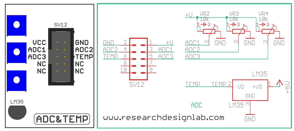
ADC
Aim: Interfacing ADC with PIC-Microcontroller.
Description: To learn how to read ADC Values and display the values in the LCD
Hardware Requirement: PIC Trainer Kit, Pikit2 Programmer, FRC cables,USB A to B cable and 12V 2A Power Adapter.
Schematic Diagram

Procedure:
1. Connect ISP port of the Trainer Kit and ISP Port of the Pickit2 Programmer using FRC cable.
2. Connect PB port and SV1 (LCD 16*2 Display) port using FRC cable as shown above.
3. Connect PA port and SV12 (ADC) port using FRC cable.
4.Connect the USB cable to the programmer and connect the Power Adapter to the PIC Trainer Kit.
5. Open MikroC Pro,write the program. Then click on Build to verify the code.
6. Open Pickit2 Software to upload the hex File (Follow the steps given in the Pickit2 User Guide).
7.Once the hex file is written successfully,Press the reset switch of the PIC Microcontroller and Vary the POT to see the Analog Values displayed on the LCD.
Code
/*
* Project name:
 PIC Development Board
* Copyright
 (c) Researchdesignlab.com
* Test configuration:
 MCU: PIC16F877A
 Dev.Board: PIC
 Oscillator: 20.0 MHz
 Software: mikroC PRO for PIC v 4.6
*/
// LCD module connections
sbit LCD_RS at RB0_bit;
sbit LCD_EN at RB1_bit;
sbit LCD_D4 at RB4_bit;
sbit LCD_D5 at RB5_bit;
sbit LCD_D6 at RB6_bit;
sbit LCD_D7 at RB7_bit;
sbit LCD_RS_Direction at TRISB0_bit;
sbit LCD_EN_Direction at TRISB1_bit;
sbit LCD_D4_Direction at TRISB4_bit;
sbit LCD_D5_Direction at TRISB5_bit;
sbit LCD_D6_Direction at TRISB6_bit;
sbit LCD_D7_Direction at TRISB7_bit;
// End LCD module connections
char txt[6];
unsigned tmp;
void main() {
 Lcd_Init(); // Initialize LCD
 Lcd_Cmd(_LCD_CLEAR); // Clear display
 Lcd_Cmd(_LCD_CURSOR_OFF); // Cursor off
 Lcd_Out(1, 1, "PIC DVLPMNT BRD"); // Write text on Lcd starting from
 Delay_ms(1000); // 1000ms delay
row 1, column 3:
 while(1)
 { // read analog value from ADC
module channel 0
 tmp = ADC_Read(0); // calulting for temp
 tmp=((tmp/1023.0)*500); // Clear display
 wordToStr(tmp, txt); //convaersion wrd to str
 Lcd_Cmd(_LCD_CLEAR); // Clear display
 Lcd_Out(2, 3, txt); // Write text on Lcd starting from
row 2, column 3:
 Delay_ms(500); // 500ms delay
 }
}
UART
Aim: Interfacing UART with PIC-Microcontroller.
Description: Transmit / Receive Data using UART and display the data’s on the terminal Software.
Hardware Requirement: PIC Trainer Kit, PicKit2 Programmer, USB to RS232 Converter, USB A to B Cable and 12V 2A Power Adapter.
Schematic Diagram

Procedure:
1. Connect ISP port of the Trainer Kit and ISP Port of the Pickit2 Programmer using FRC cable.
2. Connect the 12V 2A Power Adapter to the PIC Trainer Kit Board.
3. Open MikroC Pro, write the program. Then click on Build to verify the code.
4.Open Pickit2 Software to upload the hex File (Follow the steps given in the Pickit2 User Guide).
5. Once the hex file is written successfully, press the reset switch of the PIC Microcontroller
6. Remove the USB cable from the Board.
7. Connect the USB to RS232 converter to the Board and other side of the connector to the Computer/PC using USB Cable.
8. Make 232TX and 232RX pins of DIP2 HIGH.
9. Open any of the Terminal Software to check the output.
(Ex: Tera Term Software, To Download this Software, CLICK HERE)
Open the Tera Term Software, Click on the radio button Serial and select the Port and then click on OK.
 10. Press the Reset Button of the PIC Microcontroller, You can see the data on the terminal software.
11. Send the data from your keyboard, everything you type should be displayed in the terminal window.

Procedure:
1. Connect ISP port of the Trainer Kit and ISP Port of the Pickit2 Programmer using FRC cable.
2. Connect the 12V 2A Power Adapter to the PIC Trainer Kit Board.
3. Open MikroC Pro,write the program. Then click on Build to verify the code.
4. Open Pickit2 Software to upload the hex File (Follow the steps given in the Pickit2 User Guide)
5. Once the hex file is written successfully, press the reset switch of the PIC Microcontroller.
6. Remove the USB cable from the Board.
Code
char uart_rd;
char uart_rd;
void main() {
 UART1_Init(9600); // Initialize UART module at 9600 bps
 Delay_ms(100); // Wait for UART module to stabilize
 UART1_Write_Text("RDL");
 UART1_Write(10);
 UART1_Write(13);
 while (1) { // Endless loop
 if (UART1_Data_Ready()) { // If data is received,
 uart_rd = UART1_Read(); // read the received data,
 UART1_Write(uart_rd); // and send data via UART
 }
 }
}
Seven Segment Display
Aim: Interfacing Seven Segment Display with 8051-Microcontroller.
Description: To display numbers in the seven segment.
Hardware Requirement: 8051 Trainer Kit, FRC cables and USB A to B cable.
Schematic Diagram

Procedure:
1. Connect ISP port of the Trainer Kit and ISP port of the Pickit2 Programmer using FRC cable.
2. Connect PB port and SV4 port and Connect PD port and SV3 port using FRC cable as shown above.
3. Connect the USB cable to the programmer and connect the 12V 2A Power Adapter to the PIC Trainer Kit.
4. Open MikroC Pro, write the program. Then click on Build to verify the code.
5. Open Pickit2 Software to upload the hex File (Follow the steps given in the Pickit2 User Guide).
6. Once the hex file is written successfully,Press the reset switch of the PIC Microcontroller and you can see the numbers displayed on the Seven Segment Display.
Code
/*
* Project name:
PIC Development Board
* Copyright
(c) Researchdesignlab.com
* Test configuration:
MCU: PIC16F877A
Dev.Board: PIC
Oscillator: 20.0 MHz
Software: mikroC PRO for PIC v 4.6
*/
unsigned int portb_index,portb_array[4],digit, COUNT=0;
unsigned short mask(unsigned short num) {
switch (num) {
case 0 : return 0xC0;
case 1 : return 0xF9;
case 2 : return 0xA4;
case 3 : return 0xB0;
case 4 : return 0x99;
case 5 : return 0x92;
case 6 : return 0x82;
case 7 : return 0xF8;
case 8 : return 0x80;
case 9 : return 0x90;
} //case end
}
void interrupt() {
PORTD = 0XFF; // Turn off all 7seg displays
PORTB= portb_array[portb_index]; // bring appropriate value to PORTB
if(portb_index==0)
PORTD = 0XF7;
else if(portb_index==1) // turn on appropriate 7seg. display
PORTD = 0XFB;
else if(portb_index==2) // turn on appropriate 7seg. display
PORTD = 0XFD;
else if(portb_index==3) // turn on appropriate 7seg. display
PORTD = 0XFE;
// increment portd_index
portb_index++ ;
if (portb_index > 4u)
portb_index = 0; // turn on 1st, turn off 2nd 7seg.
TMR0 = 0; // reset TIMER0 value
INTCON = 0x20; // Clear T0IF
}
void display(unsigned int number)
{
digit = number / 1000u ; // extract thousands digit
portb_array[3] = mask(digit); // and store it to PORTB array
digit = (number / 100u) % 10u; // extract hundreds digit
portb_array[2] = mask(digit); // and store it to PORTB array
digit = (number / 10u) % 10u; // extract tens digit
portb_array[1] = mask(digit); // and store it to PORTB array
digit = number % 10u; // extract ones digit
portb_array[0] = mask(digit); // and store it to PORTB array
}
void main() {
TRISD=0X00;
TRISB=0X00;
OPTION_REG = 0x80; // Timer0 settings
digit = 0;
portb_index = 0;
TMR0 = 0;
INTCON = 0xA0; // Enable GIE, T0IE
PORTD = 0xFF;
Delay_ms(200);
COUNT=0;
while(1)
{
display(COUNT);
Delay_ms(300);
COUNT=COUNT+5;
if(COUNT>2000)
COUNT=0;
}
}
RTC (Real Time Clock)
Aim: Interfacing Real Time Clock with PIC-Microcontroller.
Description: To display Date and Time on the LCD Display using PIC Trainer Kit.
Hardware Requirement: PIC Trainer Kit, PicKit2 Programmer, FRC Cables, USB A to B Cable and 12V 2A Power Adapter.
Schematic Diagram

Procedure:
1. Connect ISP port of the Trainer Kit and ISP port of the Pickit2 Programmer using FRC cable.
2. Connect PB port and SV1 port using FRC cable as shown above.
3. Connect the USB cable to the programmer and connect the 12V 2A Power Adapter to the PIC Trainer Kit.
4. Open MikroC Pro, write the program. Then click on Build to verify the code.
5. Open Pickit2 Software to upload the hex File (Follow the steps given in the Pickit2 User Guide)
6. Once the hex file is written successfully, Press the reset switch of the PIC Microcontroller and the Date and Time will be displayed on the LCD Display.
Code
// Software I2C connections
sbit Soft_I2C_Scl at RC4_bit;
sbit Soft_I2C_Sda at RC3_bit;
sbit Soft_I2C_Scl_Direction at TRISC4_bit;
sbit Soft_I2C_Sda_Direction at TRISC3_bit;
// End Software I2C connections
// LCD module connections
sbit LCD_RS at RB0_bit;
sbit LCD_EN at RB1_bit;
sbit LCD_D4 at RB4_bit;
sbit LCD_D5 at RB5_bit;
sbit LCD_D6 at RB6_bit;
sbit LCD_D7 at RB7_bit;
sbit LCD_RS_Direction at TRISB0_bit;
sbit LCD_EN_Direction at TRISB1_bit;
sbit LCD_D4_Direction at TRISB4_bit;
sbit LCD_D5_Direction at TRISB5_bit;
sbit LCD_D6_Direction at TRISB6_bit;
sbit LCD_D7_Direction at TRISB7_bit;
// End LCD module connections
void delay()
{
 unsigned char z;
 for(z=250;z>z--)
 ;
}
void rtc_init()
{
unsigned char
a[]={0x00,0x00,0x01,0x05,0x02,0x17,0x03,0x05,0x04,0x30,0x05,0x03,0x06,0x22};
 unsigned char x=0;
 Soft_I2C_Start();
 Soft_I2C_Write(0xD0);
 Soft_I2C_Write(a[0]);
 Soft_I2C_Write(a[1]);
 Soft_I2C_Stop();
 Soft_I2C_Start();
 Soft_I2C_Write(0xD0);
 Soft_I2C_Write(a[2]);
 Soft_I2C_Write(a[3]);
 Soft_I2C_Stop();
 Soft_I2C_Start();
 Soft_I2C_Write(0xD0);
 Soft_I2C_Write(a[4]);
 Soft_I2C_Write(a[5]);
 Soft_I2C_Stop();
 Soft_I2C_Start();
 Soft_I2C_Write(0xD0);
 Soft_I2C_Write(a[8]);
 Soft_I2C_Write(a[9]);
 Soft_I2C_Stop();
 Soft_I2C_Start();
 Soft_I2C_Write(0xD0);
 Soft_I2C_Write(a[10]);
 Soft_I2C_Write(a[11]);
 Soft_I2C_Stop();
 Soft_I2C_Start();
 Soft_I2C_Write(0xD0);
 Soft_I2C_Write(a[12]);
 Soft_I2C_Write(a[13]);
 Soft_I2C_Stop();
}
void display(unsigned char a1)
{
 unsigned char b1;
 b1=(a1 & 0x0f0);
 b1=(b1>>4)+0x30;
 Lcd_Chr_Cp(b1);
 b1=(a1 & 0x0f);
 b1=b1+0x30;
 Lcd_Chr_Cp(b1);
}
void main()
{
 unsigned char i,temp,ch,hr,min,STORE_VAL=0,FLAG1=0,FLAG2=0;
 unsigned int LDR_VAL1,LDR_VAL2,LDR_VAL3;
 Lcd_Init(); // Initialize LCD
 Lcd_Cmd(_LCD_CLEAR); // Clear display
 Lcd_Cmd(_LCD_CURSOR_OFF);
 delay();
 delay();
Soft_I2C_Init();
 delay();
 rtc_init();
 while(1)
 {
 Lcd_Out(1, 1, "TIME ");
 Soft_I2C_Start();
 Soft_I2C_Write(0xD0);
delay();
Soft_I2C_Write(2);
 Delay_100ms();
 Soft_I2C_Start();
 // Soft_I2C_Write(0xD0);
 Soft_I2C_Write(0xD1);
 ch=Soft_I2C_Read(0u);
 Soft_I2C_Stop();
 hr=ch;
display(ch);
delay();
delay();
delay();
 Lcd_Chr_Cp(':');
 Soft_I2C_Start();
 Soft_I2C_Write(0xD0);
 Soft_I2C_Write(1);
 Delay_100ms();
 Soft_I2C_Start();
 //I2C1_Repeated_Start();
 Soft_I2C_Write(0xD1);
 ch=Soft_I2C_Read(0u);
 min=ch;
delay();
Soft_I2C_Stop();
delay();
display(ch);
delay();
delay();
 delay();
 Lcd_Chr_Cp(':');
 Soft_I2C_Start();
 Soft_I2C_Write(0xD0);
 Soft_I2C_Write(0);
 Delay_100ms();
 Soft_I2C_Start();
 Soft_I2C_Write(0xD1);
 ch=Soft_I2C_Read(0u);
 Soft_I2C_Stop();
 display(ch);
delay();
delay();
if(hr==0x12||hr==0x01||hr==0x02||hr==0x03||hr==0x04||hr==0x05||hr==0x06)
 {
Lcd_Chr_Cp(' ');
Lcd_Chr_Cp('A');
Lcd_Chr_Cp('M');
 }
else
{
Lcd_Chr_Cp(' ');
Lcd_Chr_Cp('P');
Lcd_Chr_Cp('M');
 }
 i=0;
Lcd_Out(2, 1, "DATE ");
 Soft_I2C_Start();
 Soft_I2C_Write(0xD0);
 Soft_I2C_Write(4);
 Delay_100ms();
Soft_I2C_Start();
 Soft_I2C_Write(0xD1);
 ch=Soft_I2C_Read(0u);
 delay();
Soft_I2C_Stop();
display(ch);
delay();
delay();
Lcd_Chr_Cp('-');
 Soft_I2C_Start();
 Soft_I2C_Write(0xD0);
 Soft_I2C_Write(5);
 Delay_100ms();
 Soft_I2C_Start();
 Soft_I2C_Write(0xD1);
 ch=Soft_I2C_Read(0u);
 delay();
 Soft_I2C_Stop();
 display(ch);
delay();
delay();
 Lcd_Chr_Cp('-');
 Soft_I2C_Start();
 Soft_I2C_Write(0xD0);
 Soft_I2C_Write(6);
 Delay_100ms();
 Soft_I2C_Start();
 Soft_I2C_Write(0xD1);
 ch=Soft_I2C_Read(0u);
 Soft_I2C_Stop();
 display(ch);
delay();
 delay();
}
}
Buzzer
Aim: Interfacing Buzzer with PIC-Microcontroller.
Description: Turning ON and OFF the Buzzer after Particular delay.
Hardware Requirement: PIC Trainer Kit, Pickit2 Programmer, FRC cables, USB A to B cable and 12V 2A Adapter.

Procedure:
1. Connect ISP port of the Trainer Kit and ISP Port of the Pickit2 Programmer using FRC cable.
2. Connect PB port and SV9 port using FRC cable as shown above.
3. Connect the USB cable to the programmer and connect the Power Adapter to the PIC Trainer Kit.
4. Open MikroC Pro,write the program.Then click on Build to verify the code.
5.Open Pickit2 Software to upload the hex File(Follow the steps given in the Pickit2 User Guide).
6. Once the hex file is written successfully,Press the reset switch of the PIC Microcontroller and Buzzer will be turned ON and OFF.
Code
/*
* Project name:
PIC Development Board LED and Keypad code
* Copyright
(c) Researchdesignlab.com
* Test configuration:
MCU: PIC16F877A
Dev.Board: PIC
Oscillator: 20.0 MHz
Software: mikroC PRO for PIC v 4.6
Developer: DD
*/
sbit BUZZER at RB0_bit; //defining PortB Pin B0 as BUZZER
void main()
{
TRISB=0x00; //defining PORTB as output port
BUZZER= 1;
Delay_ms(1000);
BUZZER= 0;
Delay_ms(1000);
while(1)
{
BUZZER=1; //binary equivalent value:00000000
Delay_ms(1000);
BUZZER=0; //binary equivalent value:11111111
Delay_ms(1000);
}
}
Relay
Aim:Interfacing Relay with PIC-Microcontroller.
Description:Turning ON and OFF the Relay after Particular delay.
Hardware Requirement: PIC Trainer Kit, Pickit2 Programmer,FRC cables,USB A to B cable and 12V 2A Adapter

Procedure:
1. Connect ISP port of the Trainer Kit and ISP Port of the Pickit2 Programmer using FRC cable.
2. Connect PB port and SV9 port using FRC cable as shown above.
3. Connect the USB cable to the programmer and connect the Power Adapter to the PIC Trainer Kit.
4. Open MikroC Pro,write the program. Then click on Build to verify the code.
5. Open Pickit2 Software to upload the hex File(Follow the steps given in the Pickit2 User Guide).
6. Once the hex file is written successfully, Press the reset switch of the PIC Microcontroller and Relay will be turned ON and OFF.
Code
PIC Development Board LED and Keypad code
* Copyright
(c) Researchdesignlab.com
* Test configuration:
MCU: PIC16F877A
Dev.Board: PIC
Oscillator: 20.0 MHz
Software: mikroC PRO for PIC v 4.6
Developer: DD
*/
sbit RELAY at RB1_bit; //defining PortB Pin B1 as RELAY
void main()
{
TRISB=0x00; //defining PORTB as output port
RELAY= 1;
Delay_ms(1000);
RELAY= 0;
Delay_ms(1000);
while(1)
{
RELAY=1; //binary equivalent value:00000000
Delay_ms(1000);
RELAY=0; //binary equivalent value:11111111
Delay_ms(1000);
}
}
Hex Keypad
Aim: To interface 4x4 Hex keypad with PIC-Microcontroller.
Description: To display the pressed key on the LCD Display.
Hardware Requirement: PIC Trainer Kit, PicKit2 Programmer, FRC Cables, USB A to B Cable and 12V 2A Power Adapter.
Schematic Diagram

Procedure:
1. Connect ISP port of the Trainer Kit and ISP Port of the Pickit2 Programmer using FRC cable.
2. Connect PD port and SV5(4*4 Key Matrix) port and Connect PB port and SV1(LCD) port using FRC cable as shown above.
3.Connect the USB cable to the programmer and connect the 12V 2A Power Adapter to the PIC Trainer Kit.
4. Open MikroC Pro,write the program.Then click on Build to verify the code.
5. Open Pickit2 Software to upload the hex File(Follow the steps given in the Pickit2 User Guide).
6. Once the hex file is written successfully,Press the reset switch of the PIC Microcontroller.
Code
sbit X_1 at RB0_bit;
sbit X_2 at RB1_bit;
sbit X_3 at RB2_bit;
sbit X_4 at RB3_bit;
sbit Y_1 at RB4_bit;
sbit Y_2 at RB5_bit;
sbit Y_3 at RB6_bit;
sbit Y_4 at RB7_bit;
#define Keypad_PORT PORTB
#define Keypad_PORT_Direction TRISB
 // LCD module connections
sbit LCD_RS at RD0_bit;
sbit LCD_EN at RD1_bit;
sbit LCD_D4 at RD4_bit;
sbit LCD_D5 at RD5_bit;
sbit LCD_D6 at RD6_bit;
sbit LCD_D7 at RD7_bit;
sbit LCD_RS_Direction at TRISD0_bit;
sbit LCD_EN_Direction at TRISD1_bit;
sbit LCD_D4_Direction at TRISD4_bit;
sbit LCD_D5_Direction at TRISD5_bit;
sbit LCD_D6_Direction at TRISD6_bit;
sbit LCD_D7_Direction at TRISD7_bit;
// End LCD module connections
char keypad_scanner(void)
{
 X_1 = 0; X_2 = 1; X_3 = 1; X_4 = 1;
 if (Y_1 == 0) { delay_ms(100); while (Y_1==0); return '1'; }
 if (Y_2 == 0) { delay_ms(100); while (Y_2==0); return '2'; }
 if (Y_3 == 0) { delay_ms(100); while (Y_3==0); return '3'; }
 if (Y_4 == 0) { delay_ms(100); while (Y_4==0); return '4'; }
 X_1 = 1; X_2 = 0; X_3 = 1; X_4 = 1;
 if (Y_1 == 0) { delay_ms(100); while (Y_1==0); return '4'; }
 if (Y_2 == 0) { delay_ms(100); while (Y_2==0); return '5'; }
 if (Y_3 == 0) { delay_ms(100); while (Y_3==0); return '6'; }
 if (Y_4 == 0) { delay_ms(100); while (Y_4==0); return '8'; }
 X_1 = 1; X_2 = 1; X_3 = 0; X_4 = 1;
 if (Y_1 == 0) { delay_ms(100); while (Y_1==0); return '7'; }
 if (Y_2 == 0) { delay_ms(100); while (Y_2==0); return '8'; }
 if (Y_3 == 0) { delay_ms(100); while (Y_3==0); return 'A'; }
 if (Y_4 == 0) { delay_ms(100); while (Y_4==0); return 'B'; }
 X_1 = 1; X_2 = 1; X_3 = 1; X_4 = 0;
 if (Y_1 == 0) { delay_ms(100); while (Y_1==0); return 'C'; }
 if (Y_2 == 0) { delay_ms(100); while (Y_2==0); return 'D'; }
 if (Y_3 == 0) { delay_ms(100); while (Y_3==0); return 'E'; }
 if (Y_4 == 0) { delay_ms(100); while (Y_4==0); return 'F'; }
 return 'n';
}
char switch_press_scan(void) // Get key from user
{
 char key = 'n'; // Assume no key pressed
 while(key=='n') // Wait untill a key is pressed
 key = keypad_scanner(); // Scan the keys again and again
 return key; //when key pressed then return its
value
}
void InitKeypad(void)
{
 Keypad_PORT = 0x00; // Set Keypad port pin
values zero
 Keypad_PORT_Direction = 0xF0; // Last 4 pins input, First 4
pins output
 OPTION_REG &= 0x7F;
}
char Key;
void main()
{
Lcd_Init(); // Initialize LCD
 Lcd_Cmd(_LCD_CLEAR);
InitKeypad();
while(1)
{
Key = switch_press_scan();
Lcd_Chr_Cp(Key);
}
}
DC Motor
Aim: To interface DC Motor with PIC-Microcontroller.
Description: To rotate DC Motor using Pic Microcontroller.
Hardware Requirement: PIC Trainer Kit, PicKit2 Programmer, DC Motor, FRC Cables, USB A to B Cable and 12V 2A Power Adapter.

Procedure:
1. Connect ISP port of the Trainer Kit and ISP port of the Pickit2 Programmer using FRC cable.
2. Connect PB port and SV9 port using FRC cable as shown above.
3.Connect the DC Motor to Output Pins OP1 and OP2 of the Trainer Kit.
4. Connect the USB cable to the programmer and connect the 12V 2A Power Adapter to the PIC Trainer Kit.
5. Open MikroC Pro,write the program.Then click on Build to verify the code.
6. Open Pickit2 Software to upload the hex File(Follow the steps given in the Pickit2 User Guide).
7. Once the hex file is written successfully,Press the reset switch of the PIC Microcontroller and you can see the DC Motor rotating.
Code
/*Oscillator: 20.0 MHz
Software: mikroC PRO for PIC v 4.6
Developer: DD
*/
sbit MOTOR1 at RB4_bit; //defining PortB Pin B4 as Motor1
sbit MOTOR2 at RB5_bit; //defining PortB Pin B5 as Motor2
void main()
{
TRISB=0x00; //defining PORTB as output port
MOTOR1=0;
MOTOR2=0;
Delay_ms(300);
while(1)
{
MOTOR1=1;
Delay_ms(1000);
MOTOR1=0;
Delay_ms(1000);
MOTOR2=1;
Delay_ms(1000);
MOTOR2=0;
Delay_ms(1000);
}
}
On Board Programming
Download and Install the Tiny PIC Bootloader,CLICK HERE

1. Once the Software gets Opened, Select your Com Port and click on Check PIC.
2. Press the Reset switch of the PIC Controller.
 3. You will get the Notification as Found 16F877A.
 4. Browse your hex file(Ex:RTC) and click on Open.
 5. Click on Write Flash.
6. Press the Reset switch of the PIC Controller.
7. You will get WRITE OK message.