Directions to select the ATmega328 Board on Arduino IDE
Installing the ATmega328 Board in Arduino IDE
Before starting this method, make sure you have the latest version of the Arduino IDE 1.8.19 installed in your computer.
If you don’t, install it from https://www.arduino.cc/en/software, continue with this tutorial.
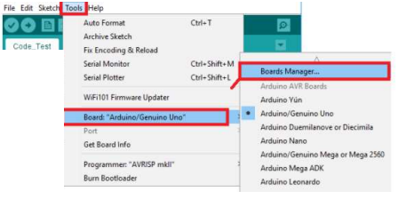
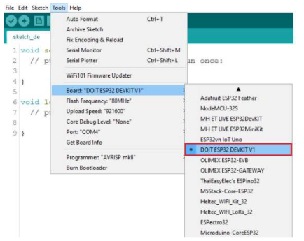
Step 1 : Plug the ESP32 Trainer Kit to your computer. With your Arduino IDE open, follow these steps: Step 2 : Select your Board in Tools > Board menu (it’s the Arduino Uno)

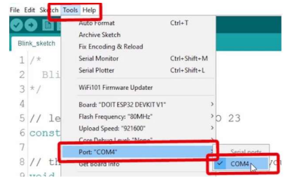
Select the Port if you don’t see the COM Port in your Arduino IDE, you need to install the FTDI Drivers: https://ftdichip.com/drivers/d2xx-drivers/
For Installation Guide, CLICK HERE

Installing Libraries
Step 1: To install a new library into your Arduino IDE. Open the IDE and click to the "Sketch" menu and then Include Library ![]() Manage Libraries.
Manage Libraries.
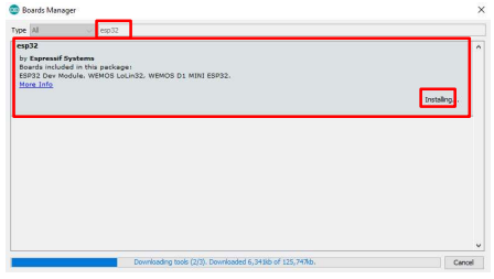
Step 2: Then the Library Manager will open and you will find a list of libraries that are already installed or ready for installation. In this example we will install the RTC library(i.e rtclib).Enter the library name to find it, click on it, then select the version of the library you want to install. Sometimes only one version of the library is available.Then click on install.If you don’t find the library then refer page 12.
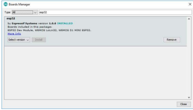
Step 3: Wait for the IDE to install the new library. Downloading may take time depending on your connection speed. Once it has finished, an Installed tag should appear next to the RTC library. Then click on close.
Another Method for installing and importing a .zip Library
Step 1: Go to Google, search for the library (i.e rtclib) you want to install, click on download ZIP.
Step 2: In the Arduino IDE, go to Sketch ![]() Include Library
Include Library ![]() Add .ZIP Library.
Add .ZIP Library.
Step 3: Select the library you would like to add. Go to the .zip file's downloaded location and open it.
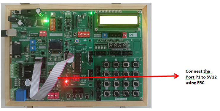
Blinking an LED
Aim: Interfacing LED’s with ATmega328 - Microcontroller.
Description: To learn how to programme an ATmega328 - Microcontroller to blink an LED by connecting an LED’s to its digital pins.
Hardware Requirement: ATmega328 IoT Development Kit and FRC cable.
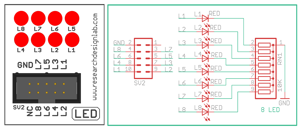
Schematic Diagram
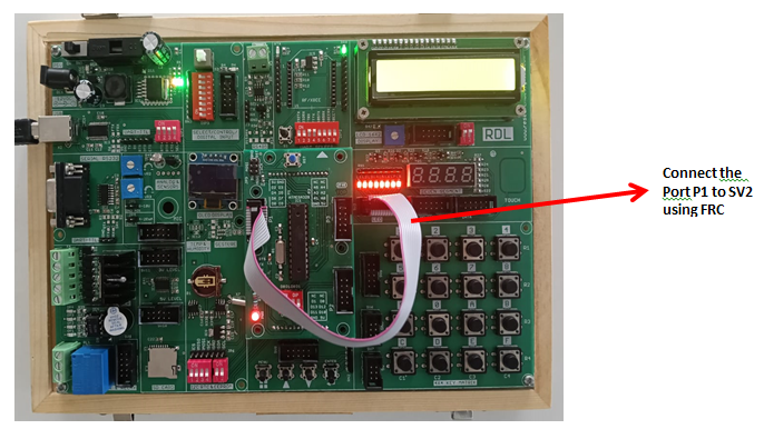
Wiring Diagram
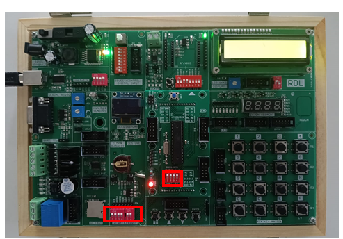
Procedure:
1. Connect P1 port and SV2 (LED) port using FRC cable as shown above.
2. Connect the USB cable to the board.
3. Open Arduino IDE. Select Arduino Uno in boards and select COM port.
4. Now write the program, verify and Upload it.
5. Now you can see the LED blink on the ATmega328 development board.
Code
const int L1=2, L2=3, L3=4, L4=5, L5=6, L6=7, L7=8, L8=9; //initializing LED pins
void setup()
{
pinMode(L1, OUTPUT); // Set all Port P1 pins as output
pinMode(L2, OUTPUT);
pinMode(L3, OUTPUT);
pinMode(L4, OUTPUT);
pinMode(L5, OUTPUT);
pinMode(L6, OUTPUT);
pinMode(L7, OUTPUT);
pinMode(L8, OUTPUT);
}
void loop()
{
digitalWrite(L1, HIGH);
digitalWrite(L2, HIGH);
digitalWrite(L3, HIGH);
digitalWrite(L4, HIGH);
digitalWrite(L5, HIGH);
digitalWrite(L6, HIGH);
digitalWrite(L7, HIGH);
digitalWrite(L8, HIGH);
delay(2000);
digitalWrite(L1, LOW);
digitalWrite(L2, LOW);
digitalWrite(L3, LOW);
digitalWrite(L4, LOW);
digitalWrite(L5, LOW);
digitalWrite(L6, LOW);
digitalWrite(L7, LOW);
digitalWrite(L8, LOW);
delay(2000);
}
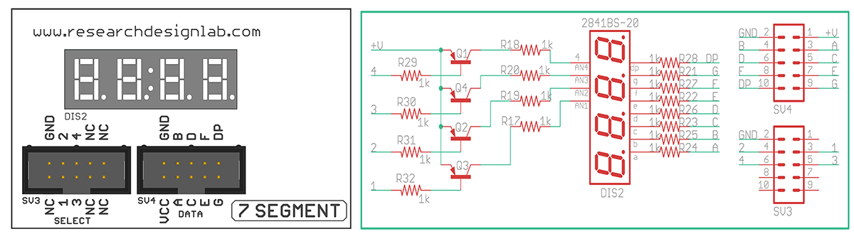
Seven Segment Displays
Aim: Interfacing ATmega328 - Microcontroller with seven segment display.
Description: To display numbers in 7 segment display.
Hardware Requirement: ESP32 - Microcontroller Development board and FRC Cables.
Schematic Diagram
Procedure:
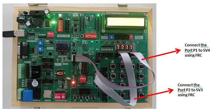
1. Connect P1 port and SV4 (Data) port and connect P2 port and SV3 (Select) port using FRC cable as shown above.
2. Connect the USB cable to the board.
3. Open Arduino IDE .Select Arduino Uno in boards and select COM port.
4. Now write the program, verify and Upload it.
5. Now you can see that number starts displaying on the seven segments on the ATmega328 development board.
Code
const int sel1 = 10, sel2 = 11, sel3 = 12, sel4 = 13;   // Selection pins
const int a = 2, b = 3, c = 4, d = 5, e = 6, f = 7, g = 8, dp = 9; // Segment pins

void setup()
{
  pinMode(sel1, OUTPUT);
  pinMode(sel2, OUTPUT);
  pinMode(sel3, OUTPUT);
  pinMode(sel4, OUTPUT);

  digitalWrite(sel1, LOW);
  digitalWrite(sel2, LOW);
  digitalWrite(sel3, LOW);
  digitalWrite(sel4, LOW);

  pinMode(a, OUTPUT);
  pinMode(b, OUTPUT);
  pinMode(c, OUTPUT);
  pinMode(d, OUTPUT);
  pinMode(e, OUTPUT);
  pinMode(f, OUTPUT);
  pinMode(g, OUTPUT);
  pinMode(dp, OUTPUT);

  delay(100);
}

void loop()
{

// 0
digitalWrite(a, LOW);
digitalWrite(b, LOW);
digitalWrite(c, LOW);
digitalWrite(d, LOW);
digitalWrite(e, LOW);
digitalWrite(f, LOW);
digitalWrite(g, HIGH);
digitalWrite(dp, LOW);
delay(2000);

// 1
digitalWrite(a, HIGH);
digitalWrite(b, LOW);
digitalWrite(c, LOW);
digitalWrite(d, HIGH);
digitalWrite(e, HIGH);
digitalWrite(f, HIGH);
digitalWrite(g, HIGH);
digitalWrite(dp, HIGH);
delay(2000);

// 2
digitalWrite(a, LOW);
digitalWrite(b, LOW);
digitalWrite(c, HIGH);
digitalWrite(d, LOW);
digitalWrite(e, LOW);
digitalWrite(f, HIGH);
digitalWrite(g, LOW);
digitalWrite(dp, LOW);
delay(2000);

// 3
digitalWrite(a, LOW);
digitalWrite(b, LOW);
digitalWrite(c, LOW);
digitalWrite(d, LOW);
digitalWrite(e, HIGH);
digitalWrite(f, HIGH);
digitalWrite(g, LOW);
digitalWrite(dp, LOW);
delay(2000);

// 4
digitalWrite(a, HIGH);
digitalWrite(b, LOW);
digitalWrite(c, LOW);
digitalWrite(d, HIGH);
digitalWrite(e, HIGH);
digitalWrite(f, LOW);
digitalWrite(g, LOW);
digitalWrite(dp, LOW);
delay(2000);

// 5
digitalWrite(a, LOW);
digitalWrite(b, HIGH);
digitalWrite(c, LOW);
digitalWrite(d, LOW);
digitalWrite(e, HIGH);
digitalWrite(f, LOW);
digitalWrite(g, LOW);
digitalWrite(dp, LOW);
delay(2000);

// 6
digitalWrite(a, LOW);
digitalWrite(b, HIGH);
digitalWrite(c, LOW);
digitalWrite(d, LOW);
digitalWrite(e, LOW);
digitalWrite(f, LOW);
digitalWrite(g, LOW);
digitalWrite(dp, LOW);
delay(2000);

// 7
digitalWrite(a, LOW);
digitalWrite(b, LOW);
digitalWrite(c, LOW);
digitalWrite(d, HIGH);
digitalWrite(e, HIGH);
digitalWrite(f, HIGH);
digitalWrite(g, HIGH);
digitalWrite(dp, HIGH);
delay(2000);

// 8
digitalWrite(a, LOW);
digitalWrite(b, LOW);
digitalWrite(c, LOW);
digitalWrite(d, LOW);
digitalWrite(e, LOW);
digitalWrite(f, LOW);
digitalWrite(g, LOW);
digitalWrite(dp, LOW);
delay(2000);

// 9
digitalWrite(a, LOW);
digitalWrite(b, LOW);
digitalWrite(c, LOW);
digitalWrite(d, LOW);
digitalWrite(e, HIGH);
digitalWrite(f, LOW);
digitalWrite(g, LOW);
digitalWrite(dp, LOW);
delay(2000);

}
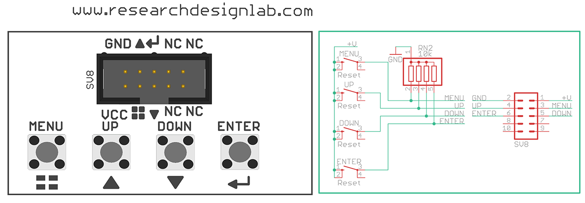
Hex Keypad
Aim: To interface 4x4 Hex Keypad with ATmega328-Microcontroller module.
Description: To display the pressed key on the serial monitor.
Hardware Requirement: ATmega328 - Microcontroller Development board and FRC Cable.
Schematic Diagram
Procedure:
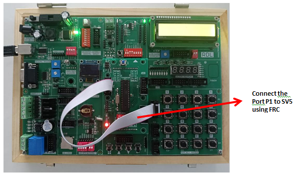
1. Connect P1 port and SV5(4*4 Key Matrix) port using FRC cable as shown above.
2. Connect the USB cable to the board.
3. Open Arduino IDE .Select Arduino Uno in boards and select COM port.
4. Now write the program, verify and Upload it.
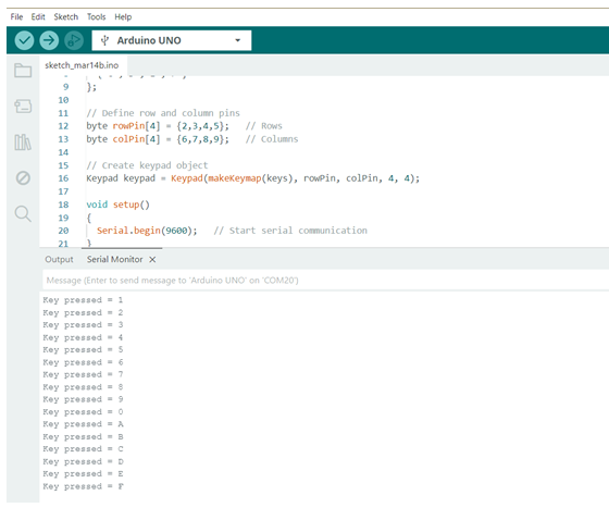
5. After uploading is done open serial monitor to observe the output.
6. On your serial monitor, the number appears for each switch pressed.
Code
#include <Keypad.h>

// Define keypad characters
char keys[4][4] = {
  {'1','2','3','4'},
  {'5','6','7','8'},
  {'9','0','A','B'},
  {'C','D','E','F'}
};

// Define row and column pins
byte rowPin[4] = {2,3,4,5};   // Rows
byte colPin[4] = {6,7,8,9};   // Columns

// Create keypad object
Keypad keypad = Keypad(makeKeymap(keys), rowPin, colPin, 4, 4);

void setup()
{
  Serial.begin(9600);   // Start serial communication
}

void loop()
{
  char pressed = keypad.getKey();   // Read key

  if (pressed)   // If a key is pressed
  {
    Serial.print("Key pressed = ");
    Serial.println(pressed);
  }

  delay(500);
}
Output
Liquid Crystal Display
Aim: To interface LCD display with ATmega328-Microcontroller module.
Description: To display the message on the LCD screen.
Hardware Requirement: ATmega328-Microcontroller Development board and FRC Cable.
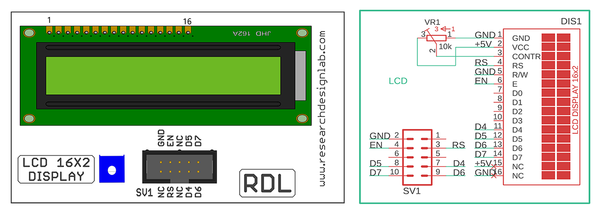
Schematic Diagram
Procedure:
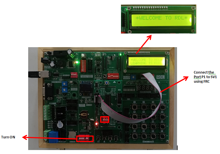
1. Connect P1 port and SV1(LCD 16*2 Display) port using FRC cable as shown above.
2. Connect the USB cable to the board.
3. Open Arduino IDE .Select Arduino Uno in boards and select COM port.
4. Write the program, verify and Upload it.
5. Now you can see the output on LCD.
Code
#include<LiquidCrystal.h> // Include the LCD library
LiquidCrystal lcd(2,3,6,7,8,9); //Port P1 Mapping the pins with library
void setup()
{
Serial.begin(9600); //Baud Rate
lcd.begin(16,2); //initializing 16X2 LCD display
}
void loop()
{
lcd.setCursor(0,0); //first line in display
lcd.print("*WELCOME TO RDL*");
delay(3000);
//lcd.clear();
lcd.setCursor(0,1); //second line in display
lcd.print("LEARNING IS FUN");
delay(3000);
lcd.clear();
}
IR (Infrared) Sensor
Aim: To Interfacing IR sensor with ATmega328-Microcontroller module.
Description: To learn how to read values from an IR sensor using ATmega328-Microcontroller
Hardware Requirement: ESP32-Microcontroller Development board, IR sensor, F-F Patch Chords.
Diagram
Procedure:
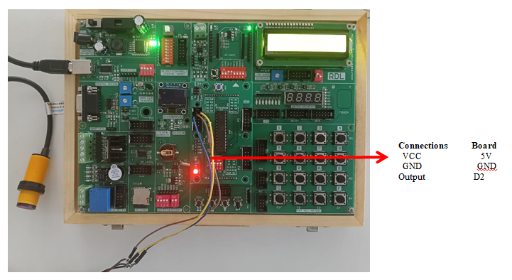
1. Connect P1 port pins (5, GND, 3V) to IR Sensor pins (OUT, GND, 5V) using patch chords (jumper wires) as shown above.
2. Connect the USB cable to the board.
3. Open Arduino IDE .Select Arduino Uno in boards and select COM port.
4. Write the program, verify and Upload it.
5. Now you can see the output on the serial monitor.
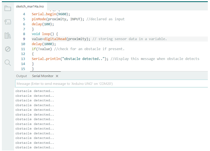
Code
const int proximity=2; //D2 of port P1 connected to IR sensor
int value=0;
void setup() {
Serial.begin(9600);
pinMode(proximity, INPUT); //declared as input
delay(100);
}
void loop() {
value=digitalRead(proximity); // storing sensor data in a variable.
delay(1000);
if(!value) //check for an obstacle if present.
{
Serial.println("obstacle detected.."); //display this message when obstacle detects
}
}
Output
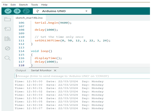
RTC (Real Time Clock)
Aim: Interfacing Real Time Clock module with ATmega328-Microcontroller module.
Description: To display Date and Time on the serial monitor using ATmega328 microcontroller development board.
Hardware Requirement: ATmega328-Microcontroller Development board and RTC Battery.
Schematic Diagram
Procedure:
1. Connect the USB cable to the board
2. Open Arduino IDE. Select Arduino Uno in boards and select COM port
3. Write the program, verify and Upload it.
4. Open the serial monitor to observe the output.
Code
#include "Wire.h"
#define DS1307_I2C_ADDRESS 0x68
// Convert normal decimal numbers to binary coded decimal
byte decToBcd(byte val){
return( (val/10*16) + (val%10) );
}
// Convert binary coded decimal to normal decimal numbers
byte bcdToDec(byte val){
return( (val/16*10) + (val%16) );
}
void setup(){
Wire.begin();
Serial.begin(9600);
delay(1000);
// set the initial time here:
setDS1307time(00,50,12,2,22,3,21); // DS1307 seconds, minutes,
hours, day, date, month, year
delay(1000);
}
void setDS1307time(byte second, byte minute, byte hour, byte
dayOfWeek, byte
dayOfMonth, byte month, byte year){
// sets time and date data to DS1307
Wire.beginTransmission(DS1307_I2C_ADDRESS);
Wire.write(0); // set next input to start at the seconds
register
Wire.write(decToBcd(second)); // set seconds
Wire.write(decToBcd(minute)); // set minutes
Wire.write(decToBcd(hour)); // set hours
Wire.write(decToBcd(dayOfWeek)); // set day of week (1=Sunday,
7=Saturday)
Wire.write(decToBcd(dayOfMonth)); // set date (1 to 31)
Wire.write(decToBcd(month)); // set month
Wire.write(decToBcd(year)); // set year (0 to 99)
Wire.endTransmission();
}
void readDS1307time(byte *second, byte *minute, byte *hour,
byte *dayOfWeek, byte *dayOfMonth, byte *month, byte *year)
{
Wire.beginTransmission(DS1307_I2C_ADDRESS);
Wire.write(0); // set DS1307 register pointer to 00h
Wire.endTransmission();
delay(100);
Wire.requestFrom(DS1307_I2C_ADDRESS, 7);
// request seven bytes of data from DS1307 starting from
register 00h
*second = bcdToDec(Wire.read() & 0x7f);
*minute = bcdToDec(Wire.read());
*hour = bcdToDec(Wire.read() & 0x3f);
*dayOfWeek = bcdToDec(Wire.read());
*dayOfMonth = bcdToDec(Wire.read());
*month = bcdToDec(Wire.read());
*year = bcdToDec(Wire.read());
Wire.endTransmission();
}

void displayTime(){
byte second, minute, hour, dayOfWeek, dayOfMonth, month, year;
// retrieve data from DS1307
readDS1307time(&second, &minute, &hour, &dayOfWeek,
&dayOfMonth, &month,
&year);
// send it to the serial monitor
Serial.print(hour, DEC);
// convert the byte variable to a decimal number when
displayed
Serial.print(":");
if (minute<10){
Serial.print("0");
}
Serial.print(minute, DEC);
Serial.print(":");
if (second<10){
Serial.print("0");
}
Serial.print(second, DEC);
Serial.print(" ");
Serial.print(dayOfMonth, DEC);
Serial.print("/");
Serial.print(month, DEC);
Serial.print("/");
Serial.print(year, DEC);
Serial.print(" Day of week: ");
switch(dayOfWeek){
case 1:
Serial.println("Sunday");
break;
case 2:
Serial.println("Monday");
break;
case 3:
Serial.println("Tuesday");
break;
case 4:
Serial.println("Wednesday");
break;
case 5:
Serial.println("Thursday");
break;
case 6:
Serial.println("Friday");
break;
case 7:
Serial.println("Saturday");
break;
}
}
void loop(){
displayTime(); // display the real-time clock data on the
Serial Monitor,
delay(1000); // every second
}
Output
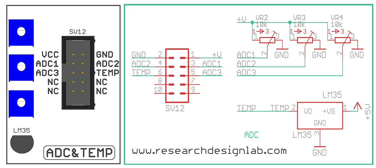
ADC
Aim: To Interface ADC with ATmega328- Microcontroller Module.
Description: To learn how to read ADC values using ATmega328-Microcontroller.
Hardware Requirement: ATmega328-Microcontroller Development board and FRC Cable.
Schematic Diagram
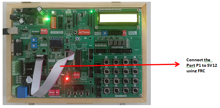
Procedure:
1. Connect P3 port and SV12(ADC & Temp) port using FRC cable as shown above.
2. Connect the USB cable to the board.
3. Open Arduino IDE . Select Arduino Uno in boards and select COM port.
4. Write the program, verify and Upload it.
5. Open the serial monitor to observe the output.
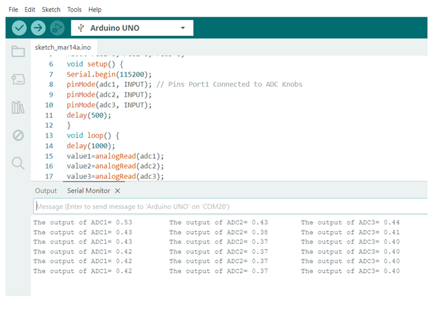
Code
const int adc1=0;
const int adc2=1;
const int adc3=2;
int value1=0, value2=0, value3=0;
float res1=0, res2=0, res3=0;
void setup() {
Serial.begin(115200);
pinMode(adc1, INPUT); // Pins Port1 Connected to ADC Knobs
pinMode(adc2, INPUT);
pinMode(adc3, INPUT);
delay(500);
}
void loop() {
delay(1000);
value1=analogRead(adc1);
value2=analogRead(adc2);
value3=analogRead(adc3);
res1=float((value1*3.3)/4095); //3.3v is maximum voltageapplied as a input
res2=float((value2*3.3)/4095); //it is 12bit ADC hencedividing by 4095 gives actual voltage
res3=float((value3*3.3)/4095);
Serial.print("The output of ADC1= ");
Serial.print(res1);
delay(500);
Serial.print("\t The output of ADC2= ");
Serial.print(res2);
delay(500);
Serial.print("\t The output of ADC3= ");
Serial.println(res3);
delay(500);
}
Output
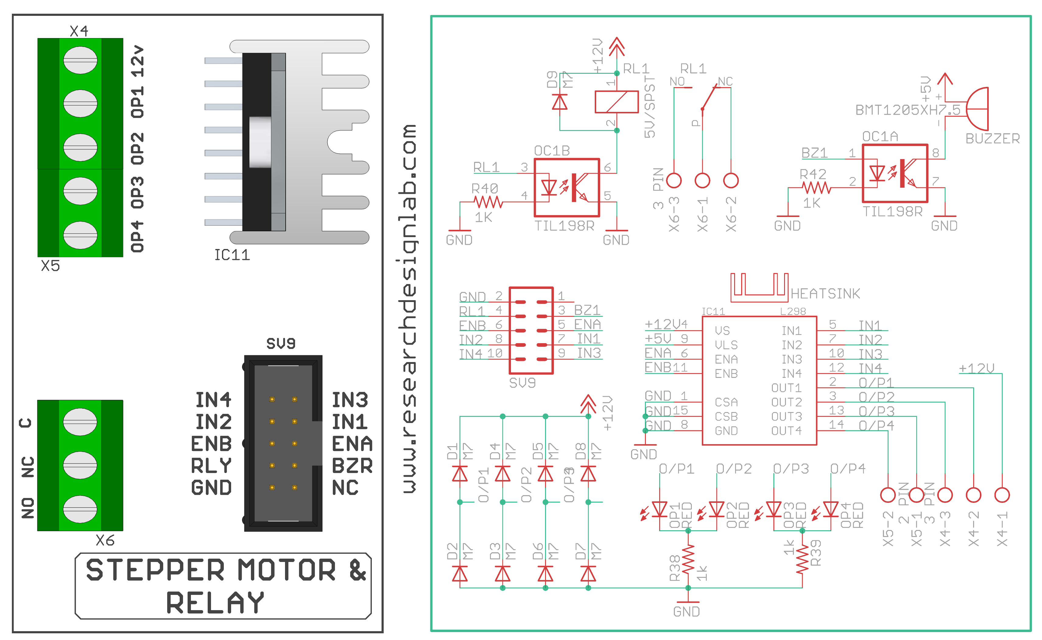
L298 Motor
Aim: To Interface L298 Motor with ATmega328-Microcontroller Board.
Description: This experiment shows how to rotate the L298 Motor clockwise and anticlockwise using ATmega328-Microcontroller.
Hardware Requirement: ATmega328-Microcontroller Development board, L298 Motor and FRC Cable.
Schematic Diagram
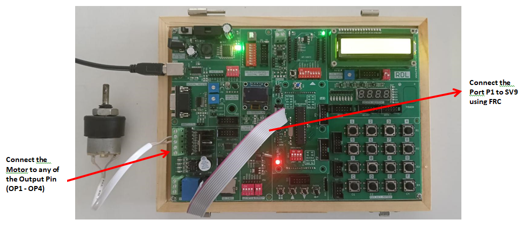
Procedure:
1. Connect P1 port and SV9 port using FRC cable.
2. Connect the USB cable to the board.
3. Open Arduino IDE. Select DOIT ESP32 DEVKIT V1in boards and select COM port.
4. Write the program, verify and Upload it.
Code
const int En1=4,En2=5; //initializing enable pins
const int in1=6, in2=7, in3=8, in4=9; //initializing input pins
void setup()
{
// channel A
pinMode(En1,OUTPUT);
pinMode(in1,OUTPUT);
pinMode(in2,OUTPUT);
// channel B
pinMode(En2,OUTPUT);
pinMode(in3,OUTPUT);
pinMode(in4,OUTPUT);
}
void loop() {
//enabling motor1
digitalWrite(En1,HIGH);
digitalWrite(En2,LOW);
// Motor 1 clockwise rotation
digitalWrite(in1,HIGH); //motor1 keep rotating for 2 seconds in clockwise direction
digitalWrite(in2,LOW);
delay(2000);
//Motor 1 anticlockwise rotation
digitalWrite(in1,LOW); //motor1 keep rotating for 2 seconds in anti-clockwise direction
digitalWrite(in2,HIGH);
delay(2000);
//enabling Motor 2
digitalWrite(En1,LOW);
digitalWrite(En2,HIGH);
// Motor 2 clockwise rotation
digitalWrite(in3,HIGH); //motor2 keep rotating for 2 seconds in clockwise direction
digitalWrite(in4,LOW);
delay(2000);
//Motor2 anticlockwise rotation
digitalWrite(in3,LOW); //motor2 keep rotating for 2 seconds in anti-clockwise direction
digitalWrite(in4,HIGH);
delay(2000);
}
SD Card
Aim: Interfacing SD card with ATmega328-Microcontroller Board to list the directories stored in memory card.
Description: To read the stored directories in SD card using ATmega328 microcontroller
development board.
Hardware Requirement: ATmega328-Microcontroller Development board and SD Card.
Schematic Diagram
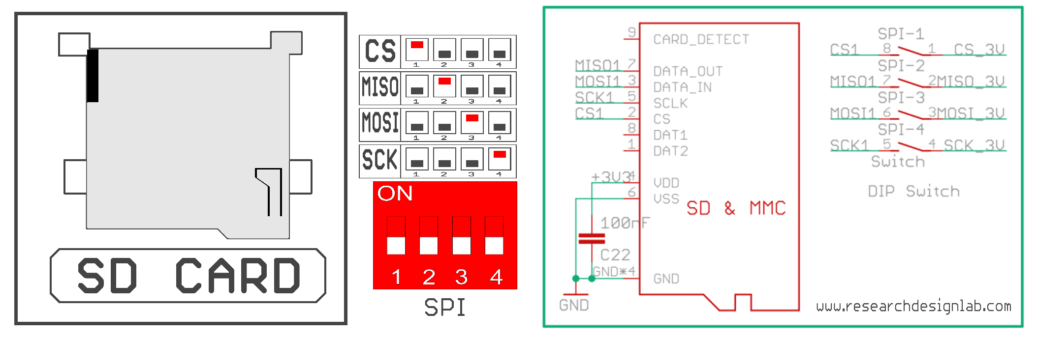
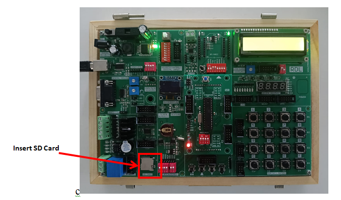
Procedure:
1. Insert the SD Card in the slot given in the board.
2. Connect the USB cable to the board.
3. Open Arduino IDE .Select Arduino Uno in boards and select COM port.
4. Write the program, verify and Upload it.
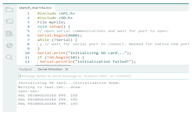
5. Open the serial monitor to observe the output.
Code
          <pre style="background-color: #fff; padding: 10px;"><code>
#include <SPI.h>
#include <SD.h>
File myFile;
void setup() {
// Open serial communications and wait for port to open:
Serial.begin(9600);
while (!Serial) {
 ; // wait for serial port to connect. Needed for native USB port only
}
Serial.print("Initializing SD card...");
if (!SD.begin(10)) {
 Serial.println("initialization failed!");
 while (1);
}
Serial.println("initialization done.");
// open the file. note that only one file can be open at atime,
// so you have to close this one before opening another.
myFile = SD.open("test.txt", FILE_WRITE);
// if the file opened okay, write to it:
if (myFile) {
 Serial.print("Writing to test.txt...");
 myFile.println("RDL TECHNOLOGIES PVT. LTD");
 // close the file:
 myFile.close();
 Serial.println("done.");
 } else {
 // if the file didn't open, print an error:
 Serial.println("error opening test.txt");
}
// re-open the file for reading:
myFile = SD.open("test.txt");
if (myFile) {
 Serial.println("test.txt:");
 // read from the file until there's nothing else in it:
while (myFile.available()) {
 Serial.write(myFile.read());
 }
 // close the file:
 myFile.close();
} else {
 // if the file didn't open, print an error:
 Serial.println("error opening test.txt");
}
}
void loop() {
// nothing happens after setup
}
Output
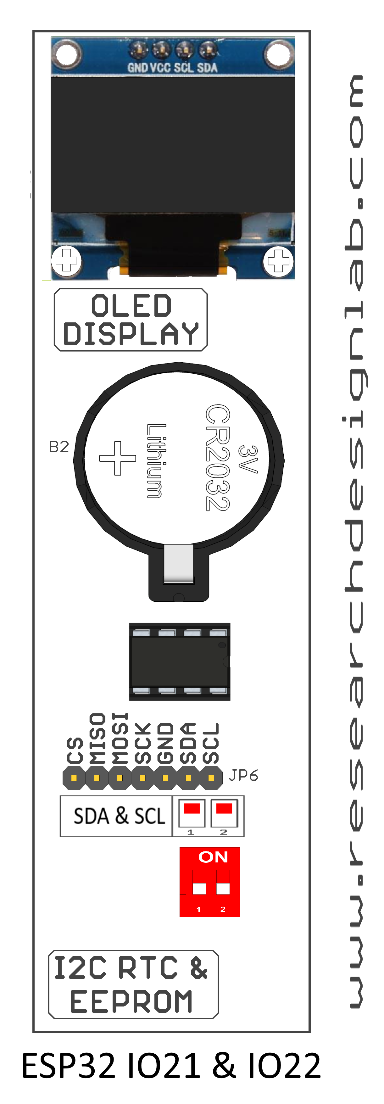
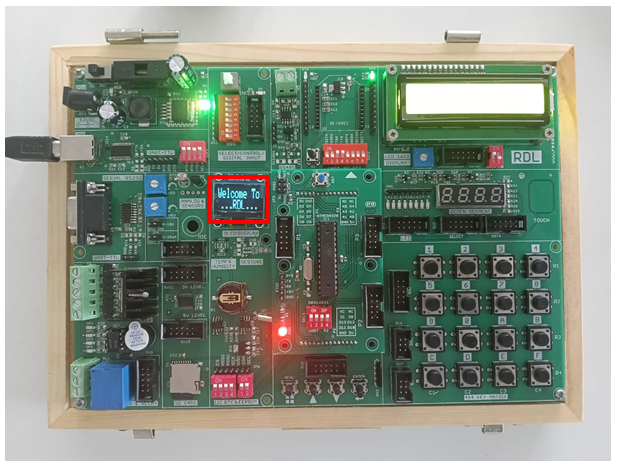
OLED
Aim: To Interface OLED Display with ATmega328-Microcontroller Board.
Description: To display message on OLED screen.
Hardware Requirement: ATmega328-Microcontroller Development board
Schematic Diagram
Procedure:
1. Connect the USB cable to the board.
2. Open Arduino IDE .Select Arduino Uno in boards and select COM port.
3. Write the program, verify and Upload it.
4. Now you can see the output displaying the message on OLED of ATmega328 microcontroller board.
Code
#include <SPI.h>
#include <Wire.h>
#include <Adafruit_GFX.h>
#include <Adafruit_SSD1306.h>
#define SCREEN_WIDTH 128 // OLED display width, in pixels
#define SCREEN_HEIGHT 32 // OLED display height, in pixels
#define OLED_RESET 4 // Reset pin
#define SCREEN_ADDRESS 0x3C //0x3C for 128x32pixels OLED
Adafruit_SSD1306 display (SCREEN_WIDTH, SCREEN_HEIGHT,
&Wire,OLED_RESET);
void setup() {
Serial.begin(9600);
if(!display.begin(SSD1306_SWITCHCAPVCC, SCREEN_ADDRESS))
//SSD1306_SWITCHCAPVCC = generate display voltage from 3.3V internally
{
Serial.println(F("SSD1306 allocation failed"));
for(;;); // Don't proceed, loop forever
}
}
void loop() {
text();
display.invertDisplay(true);
delay(2000);
display.invertDisplay(false);
delay(2000);
}
void text(void) {
display.clearDisplay();
display.setTextSize(2);
display.setTextColor(SSD1306_WHITE); // Draw white text
display.setCursor(5,3); //setting cursor on X Y plane
display.print(F("Welcome To ...RDL..."));
display.setTextColor(SSD1306_BLACK, SSD1306_WHITE); // Draw 'inverse' text
display.display();
delay(2000);
}
Temperature Sensor
Aim: To extract information from temperature sensor
Description: To learn how to read values from a temperature sensor using ATmega328-Microcontroller.
Hardware Requirement: ATmega328-Microcontroller Development board
Schematic Diagram
Procedure:
1. Connect P2 port and SV12 port using FRC cable as shown above.
2. Connect the USB cable to the board.
3. Open Arduino IDE .Select Arduino Uno in boards and select COM port.
4. Write the program, verify and Upload it.
5.Now you can see the output on the serial monitor.
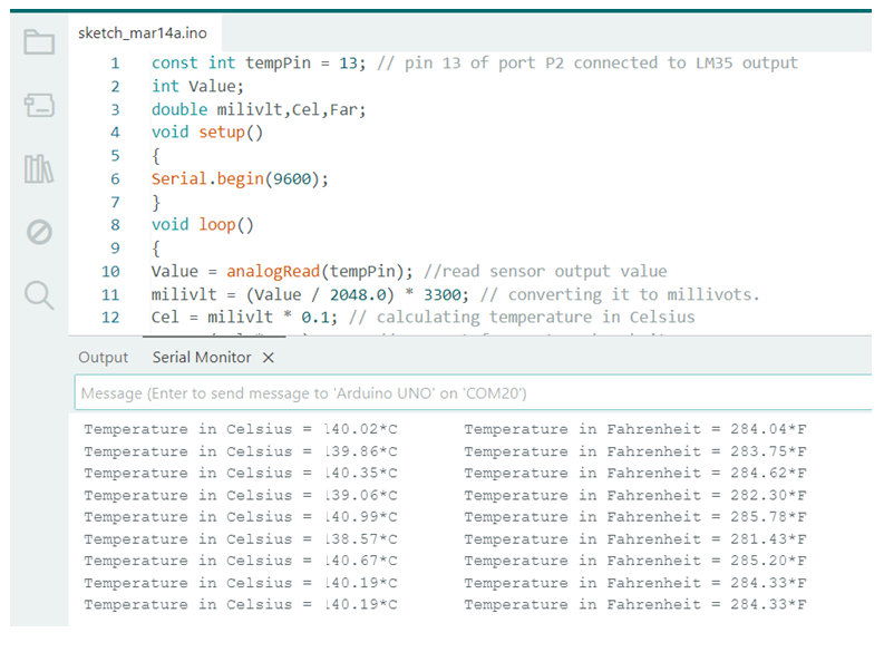
Code
const int tempPin = 13; // pin 13 of port P2 connected to LM35 output
int Value;
double milivlt,Cel,Far;
void setup()
{
Serial.begin(9600);
}
void loop()
{
Value = analogRead(tempPin); //read sensor output value
milivlt = (Value / 2048.0) * 3300; // converting it to millivots.
Cel = milivlt * 0.1; // calculating temperature in Celsius
Far = (Cel * 1.8) + 32; // convert from C to Fahrenheit
Serial.print(" Temperature in Celsius = ");
Serial.print(Cel);
Serial.print("*C");
Serial.print("\t Temperature in Fahrenheit = ");
Serial.print(Far);
Serial.println("*F");
delay(2000); //check the temperature every 2 second
}
Output