RDL742

ARM Development Board LPC2129

ARM Development Board LPC2129

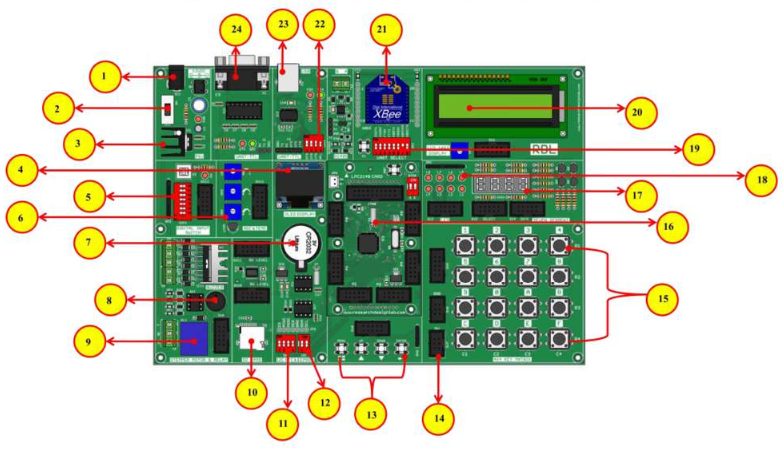
LPC2129 essential development features a plug and play design that makes it easy for connections and helps Students, hobbyists, enthusiasts, and professionals to focus more on Program/application development. LPC2129 Development Trainer Kit equipped with on board IO’s, communication interfaces & peripherals. It is really easy to design, experiment with, and test circuits without soldering. It’s used in many educational institutions and R&D LAB across the world.

Features

  •  Plug & Play Interface Connectivity.
  •  Professional EMI/RFI Complaint PCB Layout Design.
  •  Modular Block design makes Easy access & quick Prototyping.
  •  High Quality Grade PCB withwooden Enclosure.
  •  Stackable daughter board LPC2129 in-built CAN Module.
  •  On board debugging JTAG Option.
  •  Controller Area Network (CAN) transceiver.
  •  USB onboard programming .
  •  8 interfacing LED’s.
  •  1*4 interfacing keys.
  •  4*4 interfacing keypad matrix.
  •  Two channel RS232 port for communication.
  •  3 ADC potentiometer input interface.
  •  16X2 LCD, OLED interface.
  •  7Seg Multiplexed Display.
  •  On Board Power supply 3.3V, 5V 12V, GND.
  •  8 pin DIP switches.
  •  On board voltage level converter.
  •  Board enabled with the header for stacking the WiFi module.
  •  Board enabled with the header for stacking the Arduino shields.
  •  ON board Micro SD card.
  •  ON/OFF slide switch.
  •  RDL bus.
  •  External jumper nodes.
  •  Reset button.
  •  Power plug-in DC Socket.
  •  Power supply indicator LED.
  •  Test led for Tx, Rx.
  •  46 General purpose IO.
  •  FT232RL USB communication.

On board DIY projects

  • Digital clock using RTC DS1307 & 16x2 LCD.
  • Digital lock using Hex keypad & 16x2 LCD.
  • Digital password enabled access control system.
  • Temperature sensing & controlling relay.
  • Temperature sensing & speed control mirror.
  • Simple pulse input seven segment counter.
  • Realtime temperature sensing & Login to SD card.
  • Data login through RS232 serial interface with # deluminator.
  • Modbus master / stave communication.
  • Bluetooth controlled appliance through relay.
  • Timer enabled relay.
  • Motor controlling through Wi-Fi.
  • LED controlling through PC (USB Interface).
  • 4 digit random number generator.
  • Graphic icon display using OLED.
  • Menu controller LED chases.

Development Environment

Scope of Learning Experiments

  • LED blinking.
  • 8 bit LED Left shift, Right shift and Counting operation.
  • Keypad Interrupt Interface.
  • 16*2 LCD Interface.
  • Matrix Keypad Interface.
  • ADC & DAC Interface.
  • Traffic Light Signal Interface.
  • 8 bit DIP Switch Interface.
  • 7 Segment Interface.
  • L298 Driver for DC Motor and Stepper Motor Interface.
  • Elevator Interface.
  • Buzzer, Relay Interface.
  • RS485, RS232 Serial Communication.
  • UART Operation.
  • PWM Interface.
  • RTC DS1307I2C Protocol Interface.
  • AT24C04 EEPROM I2C Protocol Interface.
  • RF / WiFi Communication.
  • SPI Protocol Interface.
  • Temperature Sensor Interface.
  • Automatic Number Plate Recognition.
  • Interfacing sensor with ARM and MQTT protocol implementation.
  • Exploring MQTT Features subscribe & publish methods.
  • MQTT SSL certificate implementation - ARM.
  • Interfacing RS485 salve using Modbus protocol.
  • Interfacing BLE & Data parsing using RESTful / Json / MQTT protocol.
  • OTA Implementation - ARM.
  • Implementation of FREE RTOS on ARM.
  • Text to speech Implementation.
  • Device control through speech recognition & Alexa integration.
  • Appliance control through cloud platform using MQTT protocol.
  • Environment data like temp & humidity capturing using cloud platform.
  • Modbus RTU communication and accessing data from industrial PLC.
  • Wireless TCP/IP socket connection implementation using node and server architecture.
  • Exploring Wi-Fi MESH features.
  • Bio medical sensor kit integration and connecting IoT cloud platform for prediction.
  • Exploring OPC / UA server and client implementation.
  • Implementation of ESP32 WEB server application.

Board Narration:

  • 1. Power Supply
  • 2. Power ON Switch
  • 3. Heat Sink
  • 4. ADC (Variable Resistor POT)
  • 5. OLED Display
  • 6. Digital Input Switch
  • 7. RTC Battery
  • 8. Buzzer
  • 9. Relay
  • 10. SD Card Holder
  • 11. Jumper Settings for I2C RTC
  • 12. Jumper Settings for EEPROM
  • 13. 1*4 Keypad Switches
  • 14. RDL Bus FRC Connector
  • 15. Keypad Matrix
  • 16. ARM LPC2129 Controller
  • 17. 7 Segment Display
  • 18. 2*4 LED's
  • 19. Jumper Settings for UART Selection Pin
  • 20. 16*2 LCD Display
  • 21. Wi-Fi Module
  • 22. Jumper Settings for UART TTL
  • 23. USB Port
  • 24. DB-9 Serial Female Connector

Application Wiring Diagram

Package Contains

  • Development Board with Wooden Enclosure.
  • USB Cable.
  • 12V 2A Adapter.
  • FRC Cable.

Note

Optional OLED & SDCARD modules are provided on this board, Hobbyists / Developers can make use of this module with their previous knowledge or open-source community support and we do not have the support for the optional module.