Board Features
- Professional EMI/RFI Complaint PCB Layout Design.
- Modular Block design makes Easy access & quick Prototyping.
- FRC connectivity features minimize the connection Error.
- ROHS Compliant High Quality Grade PCB with wooden Enclosure.
- Open-source Hardware RPI 0 single-core 32-bit up to 240 MHz, Flash 16 MB.
- Supported most of the open-source platforms for Custom Programming.
- The device offers multiple industrial protocols like MODBUS RTU, MODBUS TCP, JSON, MQTT and FTP and supports secure communication SSL.
- Supported most of the cloud platforms including Microsoft Azure & AWS etc.
- Supported communication over USB, WiFi, Bluetooth, and Modbus RTU and RS232.
- High Quality Grade PCB with wooden Enclosure.
- Plug & Play Interface Connectivity.
- 8 interfacing LED’s.
- 1*4 Menu keypad.
- 4*4 Matrix Keypad.
- RS232, RS485, USB communication port.
- 7 Segment Multiplexed Display.
- 16*2 LCD & OLED Display.
- ADC & DAC Card.
- 8 bit 4 Port IO.
- On Board Wi-Fi/Bluetooth Connectivity.
- 3.3 to 5V Level Converter.
- Power Supply 3.3V and 5V.
- SD CARD Interface.
- RTC & EEPROM Interface.
- DC Motor/ Stepper Motor Driver.
- Relay, Buzzer.
- 1xTemperature Sensor.
- 3x Analog Test POT.
- OTA Firmware upgrade supported.
- On Board Programming.
- Supported DC 12V Power Supply.
Scope of Learning Experiments
- LED blinking.
- 8 bit LED Left shift, Right shift and counting operation.
- Keypad Interrupt Interface.
- 6*2 LCD interface.
- Matrix Keypad Interface.
- ADC & DAC interface.
- Traffic Light Signal Interface.
- 8 bit DIP switch interface.
- 7 Segment interface.
- L298 Driver for DC Motor and Stepper Motor Interface.
- Communication using UART, I2C & SPI.
- Buzzer, Relay Interface.
- RS485, RS232 serial communication.
- RPI 0 IO Interfacing with different sensor.
- RTC DS1307I2C protocol interface.
- AT24C04 EEPROM I2C protocol interface.
- Wi-Fi Communication.
- Interfacing SD Card and handling file system.
- Interfacing sensor with & data parsing using RESTful & Json protocol.
- FTP Implementation.
- Implementation of RPI 0 WEB server application.
- Interfacing sensor with RPI O & MQTT protocol Implementation.
- Exploring MQTT features subscribe & publish methods.
- MQTT SSL certificate implementation – RPI 0.
- Interfacing RS485 salve using MODBUS protocol.
- Interfacing BLE & Data parsing using RESTful / Json / MQTT protocol.
- Text to speech implementation.
- Device control through speech recognition & Alexa integration.
- Appliance control through cloud platform using MQTT protocol.
- Environment data like temp & humidity capturing using cloud platform.
- Modbus RTU Communication and accessing data from Industrial PLC.
- Wireless TCP/IP socket connection implementation using node and server architecture.
- Exploring OPC / UA server and client Implementation.
Applications
- Generic Low-power IoT Sensor Hubs.
- Cameras for Video Streaming.
- Generic Low-power IoT Data Loggers.
- Over-the-top (OTT) Devices.
- Speech Recognition.
- Image Recognition.
- Home Automation.
- Smart Building.
- Industrial Automation.
- Smart Agriculture.
- Audio Applications.
- Health Care Applications.
- Wi-Fi enabled Toys.
- Wearable Electronics.
- Retail & Catering Applications.
Setup RPI Device
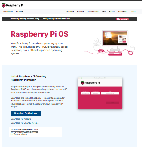
Download Raspberry Pi OS:
- Go to the official Raspberry Pi website: Raspberry Pi OS Software
- Download the "Raspberry Pi imager
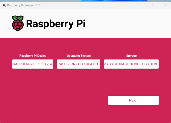
Write the Image to SD Card:
- Insert your microSD card into your computer.
- Open Raspberry Pi Imager, select the OS image, then choose the microSD card as the target.
Click "NEXT" and click EDIT SETTINGS.
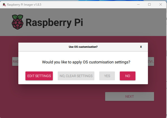
● Enter the details as per your need.
● Enter yes/Write to write OS to SD card.
● Remove SD card from System and insert to RPI SD card slot.
Install putty software or any other software to login to RPI.
HOW TO CREATE THE CODE
1. Login to RPI account.
2. Create Directory and install a virtual environment in the created directory.
a. sudo apt update.
b. sudo apt install python3 python3-pip python3-venv.
c. cd /path/to/your/project.
d. python3 -m venv myenv.
e.source myenv/bin/activate.
3. Install libraries and packages you need.
a. pip install <package-name>.
b. sudo apt update.
c. sudo apt upgrade -y.
d. sudo apt install <library_name>.
4. Create a python file and write the code in the file.
a. nano File_name.py.
5. Run the python file.
a. python file_name.py or python3 file_name.py
LED Blinking
Aim: Interface LED with RPI 0.
Description: To blink 8 LED’s with particular delay.
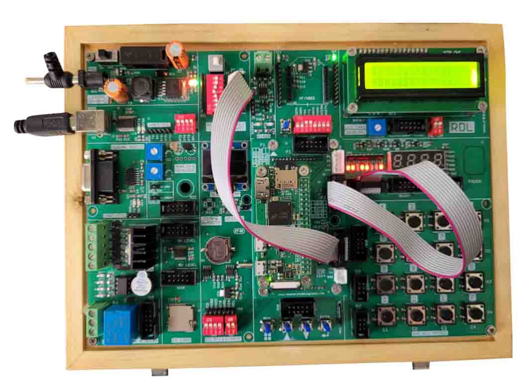
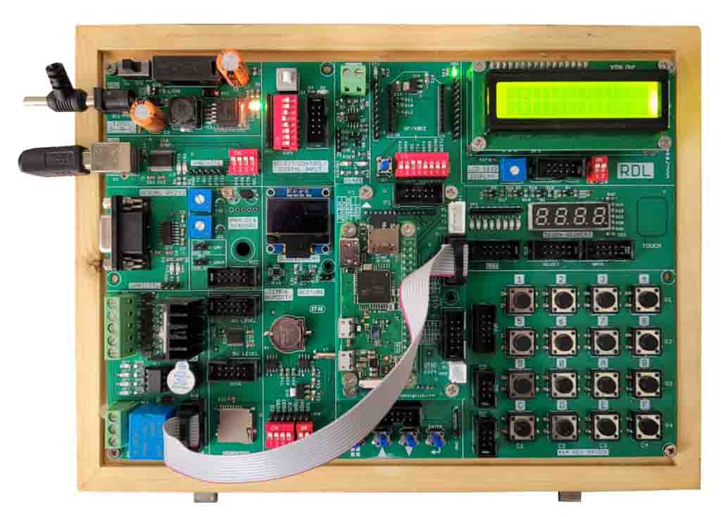
Hardware Requirement: RPI 0 Trainer Kit, power supply, FRC cable, A to B cable.
Schematic Diagram
Procedure:
1. Connect Power supply to the kit.
2. Connect the FRC cable from P2 port to SV2(LED).
3. Write the code and Run the code.
Program
import RPi.GPIO as GPIO
import time
# Define pin numbers for LEDs
led_pins = [25, 24, 23, 18, 17, 27, 22,4]
def main():
# Set GPIO mode (BOARD or BCM)
GPIO.setmode(GPIO.BCM)
# Set up LED pins as outputs
for led_pin in led_pins:
GPIO.setup(led_pin, GPIO.OUT)
GPIO.output(led_pin, GPIO.LOW) # Ensure all LEDs are off initially
try:
while True:
# Toggle each LED on and off with a 2-second delay
for led_pin in led_pins:

GPIO.output(led_pin, GPIO.HIGH) # Turn LED on
time.sleep(2) # Wait for 2 seconds
for led_pin in led_pins:
GPIO.output(led_pin, GPIO.LOW) # Turn LED off
time.sleep(2) # Wait for 2 seconds
except KeyboardInterrupt:
# Clean up GPIO on CTRL+C
GPIO.cleanup()
if __name__ == "__main__":
main()
Video
LCD Display
Aim: Interface LCD display with RPI 0.
Description: To print some text in LCD using RPI.
Hardware Requirement: RPI 0 Trainer Kit, power supply, FRC cable, A to B cable.
Procedure:
1. Connect Power supply to the kit.
2. Connect the FRC cable from P2 port to SV1(LCD).
3. Write the code and Run the code.
Program
import RPi.GPIO as GPIO
from time import sleep
# Pin configuration
RS = 25
EN = 24
D4 = 23
D5 = 17
D6 = 27
D7 = 22
# LCD Constants
LCD_WIDTH = 16
LCD_CHR = True
LCD_CMD = False
# LCD line addresses
LCD_LINE_1 = 0x80 # Address for line 1
LCD_LINE_2 = 0xC0 # Address for line 2
# Timing constants
E_PULSE = 0.0005
E_DELAY = 0.0005
def main():
# Setup GPIO
GPIO.setwarnings(False)
GPIO.setmode(GPIO.BCM)
GPIO.setup(RS, GPIO.OUT)
GPIO.setup(EN, GPIO.OUT)
GPIO.setup(D4, GPIO.OUT)
GPIO.setup(D5, GPIO.OUT)
GPIO.setup(D6, GPIO.OUT)
GPIO.setup(D7, GPIO.OUT)
# Initialize display
lcd_init()
try:
while True:
# Display messages on two lines
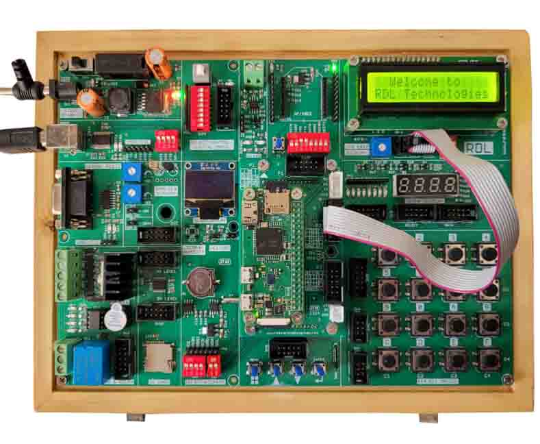
lcd_string(" Welcome to ", LCD_LINE_1)
lcd_string("RDL Technologies", LCD_LINE_2)
sleep(2) # Wait for 2 seconds
# Clear display and show a goodbye message
lcd_byte(0x01, LCD_CMD) # Clear display
lcd_string("Goodbye!", LCD_LINE_1)
sleep(2) # Wait for 2 seconds
except KeyboardInterrupt:
# Cleanup GPIO on interrupt
print("Exiting program...")
GPIO.cleanup()
def lcd_init():
lcd_byte(0x33, LCD_CMD) # 110011 Initialize
lcd_byte(0x32, LCD_CMD) # 110010 Initialize
lcd_byte(0x06, LCD_CMD) # Cursor move direction
lcd_byte(0x0C, LCD_CMD) # 000011 Display On, Cursor Off, Blink Off
lcd_byte(0x28, LCD_CMD) # Data length, number of lines, font size
lcd_byte(0x01, LCD_CMD) # Clear display
sleep(E_DELAY)
def lcd_byte(bits, mode):
GPIO.output(RS, mode)
# High bits
GPIO.output(D4, False)
GPIO.output(D5, False)
GPIO.output(D6, False)
GPIO.output(D7, False)
if bits & 0x10 == 0x10:
GPIO.output(D4, True)
if bits & 0x20 == 0x20:
GPIO.output(D5, True)
if bits & 0x40 == 0x40:
GPIO.output(D6, True)
if bits & 0x80 == 0x80:
GPIO.output(D7, True)
lcd_toggle_enable()
# Low bits
GPIO.output(D4, False)
GPIO.output(D5, False)
GPIO.output(D6, False)
GPIO.output(D7, False)
if bits & 0x01 == 0x01:
GPIO.output(D4, True)
if bits & 0x02 == 0x02:
GPIO.output(D5, True)
if bits & 0x04 == 0x04:
GPIO.output(D6, True)
if bits & 0x08 == 0x08:
GPIO.output(D7, True)
lcd_toggle_enable()
def lcd_toggle_enable():
sleep(E_DELAY)
GPIO.output(EN, True)
sleep(E_PULSE)
GPIO.output(EN, False)
sleep(E_DELAY)
def lcd_string(message, line):
message = message.ljust(LCD_WIDTH, " ")
lcd_byte(line, LCD_CMD)
for i in range(LCD_WIDTH):
lcd_byte(ord(message[i]), LCD_CHR)
if __name__ == '__main__':
main()
Seven Segment Display
Aim: Interface Seven segment display with RPI 0.
Description: To print 0-9 digits in a seven segment display using RPI
Hardware Requirement: RPI 0 Trainer Kit, power supply, FRC cables, A to B cable.
Procedure:
1. Connect Power supply to the kit.
2. Connect the FRC cable from P2 port to SV4(DATA) and P3 port to SV3(SELECT).
3. Write the code and Run the code.
Program
import RPi.GPIO as GPIO
import time
# Initialize GPIO mode
GPIO.setmode(GPIO.BCM)
# Selection pins
sel1 = 16
sel2 = 20
sel3 = 21
sel4 = 5
# Data pins
a = 25
b = 24
c = 18
d = 4
e = 23
f = 17
g = 27
dp = 22
# Setup selection pins as output
GPIO.setup(sel1, GPIO.OUT)
GPIO.setup(sel2, GPIO.OUT)
GPIO.setup(sel3, GPIO.OUT)
GPIO.setup(sel4, GPIO.OUT)
# Select all 4 digits of 7-Segment display by making them LOW
GPIO.output(sel1, GPIO.LOW)
GPIO.output(sel2, GPIO.LOW)
GPIO.output(sel3, GPIO.LOW)
GPIO.output(sel4, GPIO.LOW)
# Setup data pins as output
GPIO.setup(a, GPIO.OUT)
GPIO.setup(b, GPIO.OUT)
GPIO.setup(c, GPIO.OUT)
GPIO.setup(d, GPIO.OUT)
GPIO.setup(e, GPIO.OUT)
GPIO.setup(f, GPIO.OUT)
GPIO.setup(g, GPIO.OUT)
GPIO.setup(dp, GPIO.OUT)
time.sleep(0.1) # Delay to ensure setup is complete
def display_digit(digit):
# Define the segment states for each digit
digits = {
0: [GPIO.LOW, GPIO.LOW, GPIO.LOW, GPIO.LOW, GPIO.LOW, GPIO.LOW,
GPIO.HIGH, GPIO.LOW],
1: [GPIO.HIGH, GPIO.LOW, GPIO.LOW, GPIO.HIGH, GPIO.HIGH, GPIO.HIGH,
GPIO.HIGH, GPIO.HIGH],
2: [GPIO.LOW, GPIO.LOW, GPIO.HIGH, GPIO.LOW, GPIO.LOW, GPIO.HIGH,
GPIO.LOW, GPIO.LOW],
3: [GPIO.LOW, GPIO.LOW, GPIO.LOW, GPIO.LOW, GPIO.HIGH, GPIO.HIGH,
GPIO.LOW, GPIO.LOW],
4: [GPIO.HIGH, GPIO.LOW, GPIO.LOW, GPIO.HIGH, GPIO.HIGH, GPIO.LOW,
GPIO.LOW, GPIO.LOW],
5: [GPIO.LOW, GPIO.HIGH, GPIO.LOW, GPIO.LOW, GPIO.HIGH, GPIO.LOW,
GPIO.LOW, GPIO.LOW],
6: [GPIO.LOW, GPIO.HIGH, GPIO.LOW, GPIO.LOW, GPIO.LOW, GPIO.LOW,
GPIO.LOW, GPIO.LOW],
7: [GPIO.LOW, GPIO.LOW, GPIO.LOW, GPIO.HIGH, GPIO.HIGH, GPIO.HIGH,
GPIO.HIGH, GPIO.HIGH],
8: [GPIO.LOW, GPIO.LOW, GPIO.LOW, GPIO.LOW, GPIO.LOW, GPIO.LOW,
GPIO.LOW, GPIO.LOW],
9: [GPIO.LOW, GPIO.LOW, GPIO.LOW, GPIO.LOW, GPIO.HIGH, GPIO.LOW,
GPIO.LOW, GPIO.LOW],
}
# Set the segments based on the digit
segment_states = digits[digit]
GPIO.output(a, segment_states[0])
GPIO.output(b, segment_states[1])
GPIO.output(c, segment_states[2])
GPIO.output(d, segment_states[3])
GPIO.output(e, segment_states[4])
GPIO.output(f, segment_states[5])
GPIO.output(g, segment_states[6])
GPIO.output(dp, segment_states[7])
try:
while True:
for digit in range(10):
display_digit(digit)
time.sleep(2) # Delay between digits
finally:
GPIO.cleanup() # Reset GPIO settings on exit
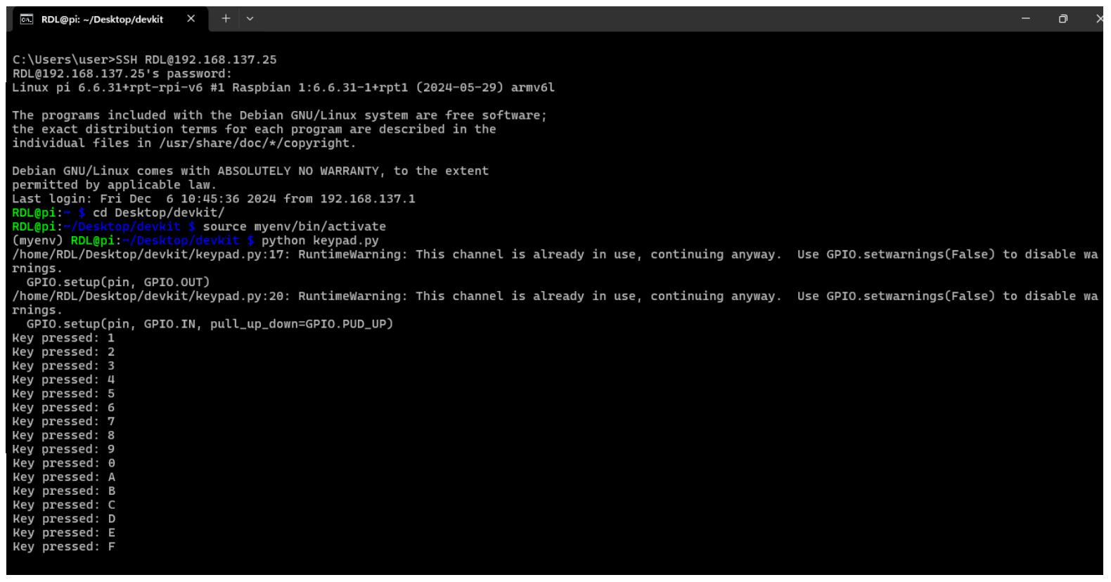
HEX Keypad
Aim: Interface Hex keypad with RPI 0.
Description: To print Hex value from hex keypad to terminal using RPI.
Hardware Requirement: RPI 0 Trainer Kit, power supply, FRC cables, A to B cable.

Procedure:
1.Connect Power supply to the kit.
2.Connect the FRC cable from P3 port to SV5.
3.Write the code and Run the code.
Program
import RPi.GPIO as GPIO
import time
# Pin definitions
row_pins = [16, 20, 21, 5]
col_pins = [6, 13, 19, 26]
keys = [
['1', '2', '3', '4'],
['5', '6', '7', '8'],
['9', '0', 'A', 'B'],
['C', 'D', 'E', 'F']
]
def init():
GPIO.setmode(GPIO.BCM)
for pin in row_pins:
GPIO.setup(pin, GPIO.OUT)
GPIO.output(pin, GPIO.HIGH)
for pin in col_pins:
GPIO.setup(pin, GPIO.IN, pull_up_down=GPIO.PUD_UP)
def get_key():
for row in range(4):
GPIO.output(row_pins[row], GPIO.LOW)
for col in range(4):
if not GPIO.input(col_pins[col]):
key = keys[row][col]
time.sleep(0.1) # Debounce delay
while not GPIO.input(col_pins[col]):
pass # Wait for key release
GPIO.output(row_pins[row], GPIO.HIGH)
return key
GPIO.output(row_pins[row], GPIO.HIGH)
return None
def main():
init()
try:
while True:
key = get_key()
if key:
print(f"Key pressed: {key}")
except KeyboardInterrupt:
GPIO.cleanup()
if __name__ == "__main__":
main()
Output
Control LED using Switch
Aim: Control LED using switch with RPI 0.
Description: To control 8 LED’s using 8 switches using RPI.
Procedure:
1.Connect Power supply to the kit.
2.Connect the FRC cable from P2 port to SV2(LED) and P3 port to SV13(switches).
3.Write the code and Run the code.
Program
import RPi.GPIO as GPIO
import time
# Define pin numbers for LEDs and switches
led_pins = [25, 24, 23, 18, 17, 27, 22]
switch_pins = [16, 20, 21, 5, 6, 13, 19]
def main():
# Set GPIO mode (BOARD or BCM)
GPIO.setmode(GPIO.BCM)
# Set up LED pins as outputs
for led_pin in led_pins:
GPIO.setup(led_pin, GPIO.OUT)
GPIO.output(led_pin, GPIO.LOW) # Ensure all LEDs are off initially
# Set up switch pins as inputs with pull-down resistors
for switch_pin in switch_pins:
GPIO.setup(switch_pin, GPIO.IN, pull_up_down=GPIO.PUD_DOWN)
try:
while True:
# Check the state of each switch and update the corresponding LED
for i in range(len(switch_pins)):
switch_state = GPIO.input(switch_pins[i])
GPIO.output(led_pins[i], switch_state)
print(f"Switch {i+1} state: {switch_state}")
time.sleep(0.1) # Small delay to debounce the switches
except KeyboardInterrupt:
# Clean up GPIO on CTRL+C
GPIO.cleanup()
if __name__ == "__main__":
main()
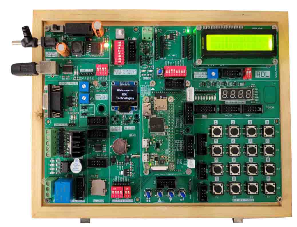
OLED
Aim: Interface OLED with RPI 0.
Description: To print some text on an OLED display using RPI.
Hardware Requirement: RPI 0 Trainer Kit, power supply, A to B cable.
Procedure:
1. Connect Power supply to the kit.
2. Write the code and Run the code.
Program
import Adafruit_SSD1306
from PIL import Image, ImageDraw, ImageFont
# Initialize the OLED display (128x64 resolution)
disp = Adafruit_SSD1306.SSD1306_128_64(rst=None)
disp.begin()
disp.clear()
disp.display()
# Create an image to draw on
width = disp.width
height = disp.height
image = Image.new('1', (width, height))
draw = ImageDraw.Draw(image)
# Load a larger font size
font_path = "/usr/share/fonts/truetype/dejavu/DejaVuSans-Bold.ttf" # Change path if needed
font_size = 15 # Adjust size as desired
font = ImageFont.truetype(font_path, font_size)
# Draw the text
draw.text((20, 5), "Welcome to", font=font, fill=255)
draw.text((50, 25), "RDL", font=font, fill=255)
draw.text((15, 45), "Technologies", font=font, fill=255)
# Display the image on the OLED
disp.image(image)
disp.display()
RTC
Aim: Interface RTC with RPI 0.
Description: To print Real Time in the terminal using RPI.
Hardware Requirement: RPI 0 Trainer Kit, power supply, A to B cable.

Procedure:
1. Connect Power supply to the kit.
2. Write the code and Run the code.
Program
import smbus
import time
# Initialize I2C bus
bus = smbus.SMBus(1)
rtc_address = 0x68
def dec_to_bcd(dec):
return (dec // 10) << 4 | (dec % 10)
def bcd_to_dec(bcd):
return (bcd & 0x0F) + ((bcd >> 4) * 10)
def set_time(year, month, day, hour, minute, second):
bus.write_byte_data(rtc_address, 0x00, dec_to_bcd(second))
bus.write_byte_data(rtc_address, 0x01, dec_to_bcd(minute))
bus.write_byte_data(rtc_address, 0x02, dec_to_bcd(hour))
bus.write_byte_data(rtc_address, 0x04, dec_to_bcd(day))
bus.write_byte_data(rtc_address, 0x05, dec_to_bcd(month))
bus.write_byte_data(rtc_address, 0x06, dec_to_bcd(year - 2000))
def read_time():
second = bcd_to_dec(bus.read_byte_data(rtc_address, 0x00))
minute = bcd_to_dec(bus.read_byte_data(rtc_address, 0x01))
hour = bcd_to_dec(bus.read_byte_data(rtc_address, 0x02))
day = bcd_to_dec(bus.read_byte_data(rtc_address, 0x04))
month = bcd_to_dec(bus.read_byte_data(rtc_address, 0x05))
year = bcd_to_dec(bus.read_byte_data(rtc_address, 0x06)) + 2000
return f"{year}-{month:02d}-{day:02d} {hour:02d}:{minute:02d}:{second:02d}"
# Set the time manually (e.g., August 12, 2024, 15:30:00)
set_time(2024, 8, 12, 15, 40, 0)
# Loop to continuously read and print the time from RTC
while True:
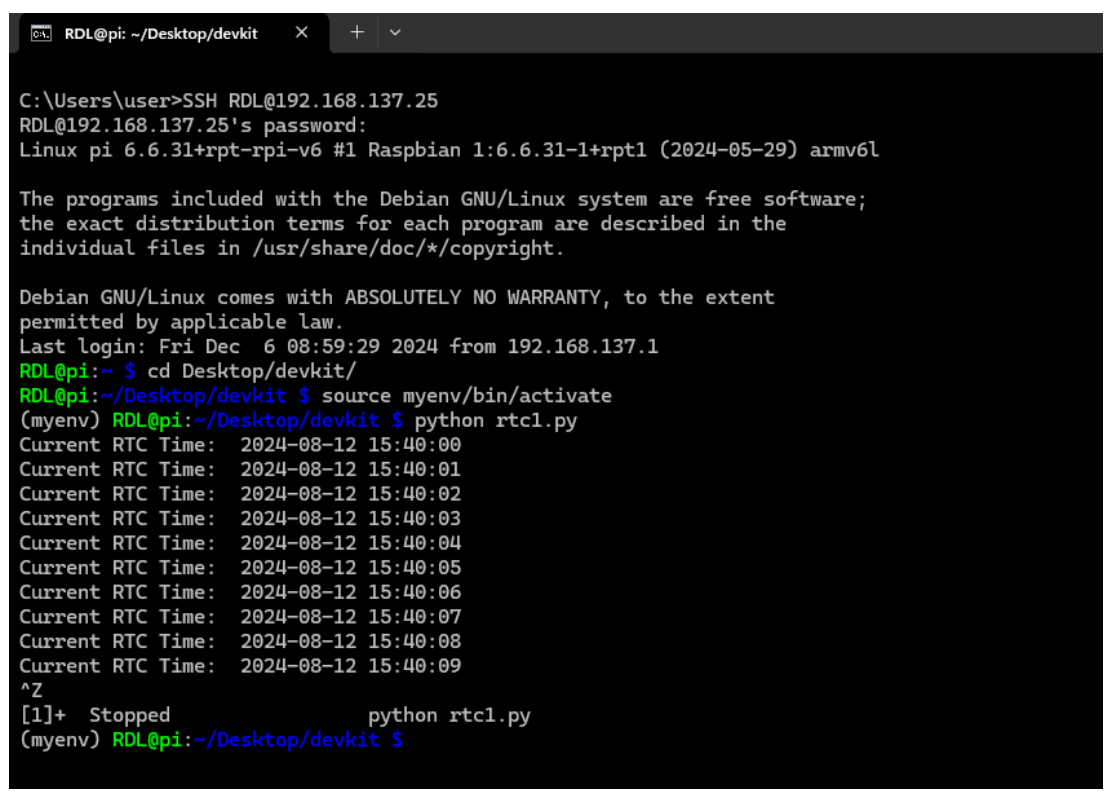
print("Current RTC Time: ", read_time())
time.sleep(1)
Output
EEPROM
Aim: Interface EEPROM with RPI 0.
Description: To operate EEPROM using RPI.
Hardware Requirement: RPI 0 Trainer Kit, power supply, A to B cable.

Procedure:
1. Connect Power supply to the kit.
2. Write the code and Run the code.
Program
import smbus
import time
# Initialize the I2C bus
bus = smbus.SMBus(1) # Use '1' for I2C on Raspberry Pi Zero
# Define the I2C address of the EEPROM (e.g., 0x50 for AT24C32)
EEPROM_ADDRESS = 0x50
# Function to write a byte to a specific EEPROM address
def write_eeprom(address, data):
bus.write_byte_data(EEPROM_ADDRESS, address, data)
time.sleep(0.01) # Wait for the write operation to complete
# Function to read a byte from a specific EEPROM address
def read_eeprom(address):
return bus.read_byte_data(EEPROM_ADDRESS, address)
# Example usage
def main():
# Write the value 42 to EEPROM address 0
write_eeprom(0x00, 42)
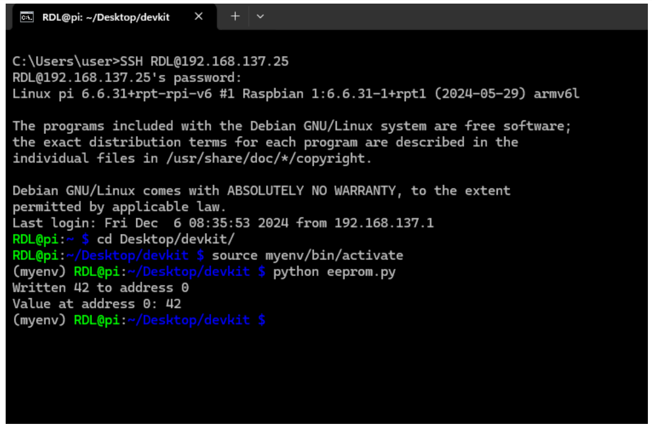
print("Written 42 to address 0")
# Read the value from EEPROM address 0
value = read_eeprom(0x00)
print(f"Value at address 0: {value}")
if __name__ == "__main__":
main()
Output:
Relay and Buzzer
Aim: Interface Relay and Buzzer with RPI 0.
Description: To toggle relay and buzzer using RPI.
Hardware Requirement: RPI 0 Trainer Kit, power supply, FRC cable, A to B cable.
Procedure
1. Connect Power supply to the kit.
2. Connect P2 port to SV9(Stepper motor,Relay & buzzer).
3. Write the code and Run the code.
Program
		  import RPi.GPIO as GPIO
import time
# Define pin numbers for LEDs
led_pins = [25, 24]
def main():
# Set GPIO mode (BOARD or BCM)
GPIO.setmode(GPIO.BCM)
# Set up LED pins as outputs
for led_pin in led_pins:
GPIO.setup(led_pin, GPIO.OUT)
GPIO.output(led_pin, GPIO.LOW) # Ensure all LEDs are off initially
try:
while True:
# Toggle each LED on and off with a 2-second delay
for led_pin in led_pins:
GPIO.output(led_pin, GPIO.HIGH) # Turn LED on
time.sleep(2) # Wait for 2 seconds
for led_pin in led_pins:
GPIO.output(led_pin, GPIO.LOW) # Turn LED off
time.sleep(2) # Wait for 2 seconds
except KeyboardInterrupt:
# Clean up GPIO on CTRL+C
GPIO.cleanup()
if __name__ == "__main__":
main()
Motor
AIM: Interface motor with RPI 0.
Description: To control motor rotation using RPI.
Hardware Required: RPI 0 Trainer Kit, power supply, FRC cable, A to B cable, Motor.
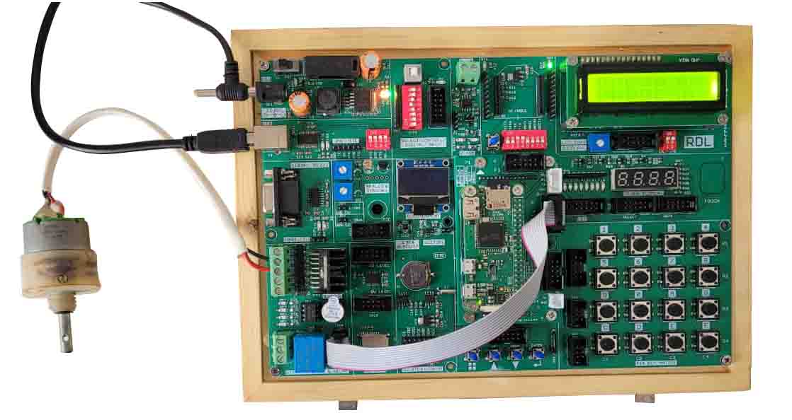
Procedure
1. Connect Power supply to the kit.
2. Connect P3 port to SV9(Stepper motor,Relay & buzzer).
3. Write the code and Run the code.
Program
import RPi.GPIO as GPIO
import time
# Set up the GPIO mode
GPIO.setmode(GPIO.BCM)
# Define the motor control pins
ENA = 21 # Motor A Enable
ENB = 5 # Motor B Enable
IN1 = 6 # Motor A Input 1
IN2 = 13 # Motor A Input 2
IN3 = 19 # Motor B Input 3
IN4 = 26 # Motor B Input 4
print("Hi")
# Set up the GPIO pins as outputs
GPIO.setup(ENA, GPIO.OUT)
GPIO.setup(ENB, GPIO.OUT)
GPIO.setup(IN1, GPIO.OUT)
GPIO.setup(IN2, GPIO.OUT)
GPIO.setup(IN3, GPIO.OUT)
GPIO.setup(IN4, GPIO.OUT)
# Set up PWM on the Enable pins
pwmA = GPIO.PWM(ENA, 10) # 100 Hz frequency
pwmB = GPIO.PWM(ENB, 10) # 100 Hz frequency
pwmA.start(0) # Start PWM with 0% duty cycle
pwmB.start(0) # Start PWM with 0% duty cycle
# Function to move motor A forward
def motorA_forward():
GPIO.output(IN1, GPIO.HIGH)
GPIO.output(IN2, GPIO.LOW)
pwmA.ChangeDutyCycle(10) # Full speed
print("motor A forward")
# Function to move motor A backward
def motorA_backward():
GPIO.output(IN1, GPIO.LOW)
GPIO.output(IN2, GPIO.HIGH)
pwmA.ChangeDutyCycle(10) # Full speed
print("motor A backward")
# Function to move motor B forward
def motorB_forward():
GPIO.output(IN3, GPIO.HIGH)
GPIO.output(IN4, GPIO.LOW)
pwmB.ChangeDutyCycle(2) # Full speed
print("motor B forward")
# Function to move motor B backward
def motorB_backward():
GPIO.output(IN3, GPIO.LOW)
GPIO.output(IN4, GPIO.HIGH)
pwmB.ChangeDutyCycle(2) # Full speed
print("motor B backward")
# Function to stop all motors
def stop_motors():
pwmA.ChangeDutyCycle(0)
pwmB.ChangeDutyCycle(0)
GPIO.output(IN1, GPIO.LOW)
GPIO.output(IN2, GPIO.LOW)
GPIO.output(IN3, GPIO.LOW)
GPIO.output(IN4, GPIO.LOW)
print("Stop")
try:
# Example usage
motorA_forward()
motorB_forward()
time.sleep(2) # Run motors for 2 seconds
stop_motors()
time.sleep(1) # Wait for 1 second
motorA_backward()
motorB_backward()
time.sleep(2) # Run motors for 2 seconds
stop_motors()
finally:
# Cleanup the GPIO pins
pwmA.stop()
pwmB.stop()
GPIO.cleanup()
print("Bye")
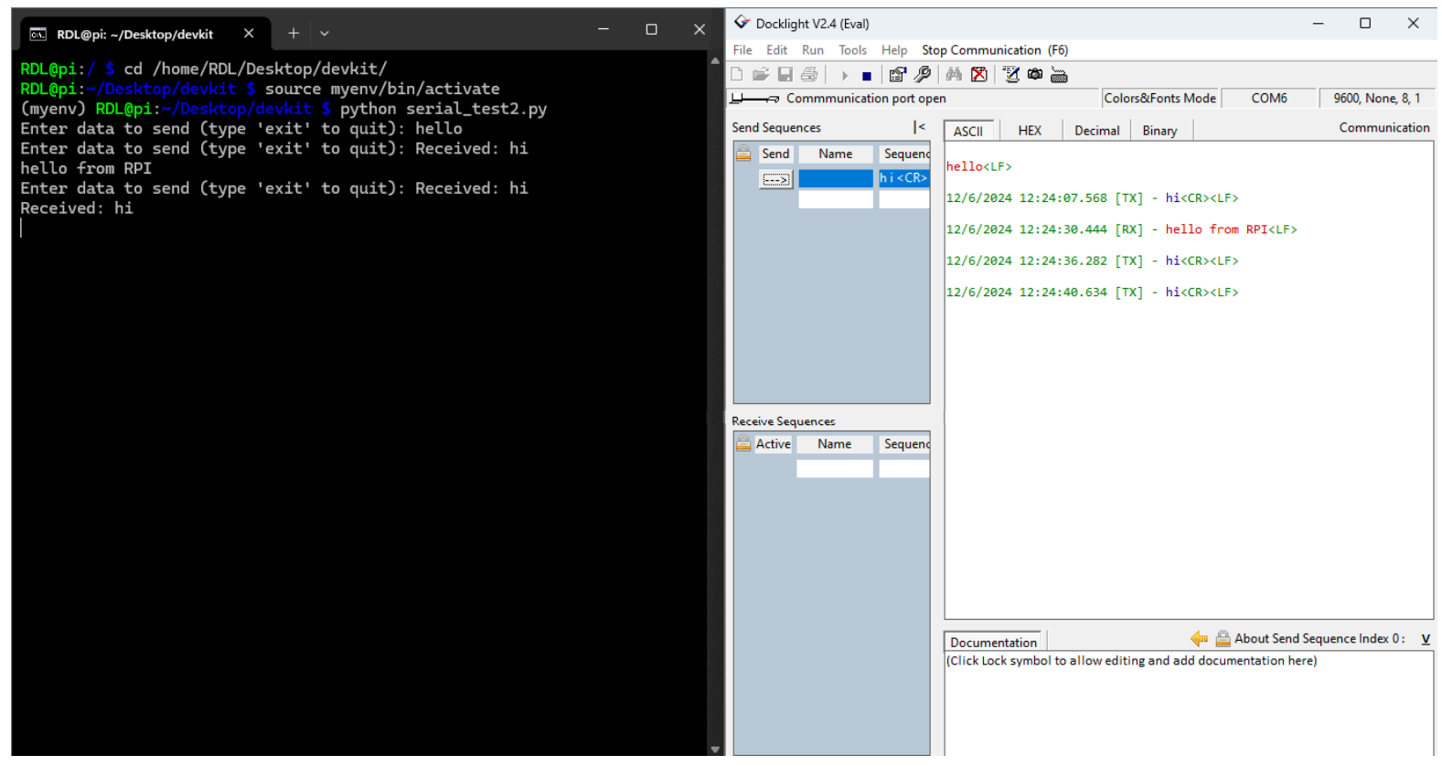
UART communication
AIM: UART communication with RPI 0.
Description: To enable data transfer with other devices using RPI.
Hardware Required: RPI 0 Trainer Kit, power supply, A to B cable.
Procedure
1. Connect Power supply to the kit.
2. Connect A-B cable to UART port.
3. Open UART communication software.
4. Write the code and Run the code.
Program
from serial import Serial
import time
import threading
# Initialize the serial connection
arduino_serial = Serial('/dev/ttyS0', 9600, timeout=0.1)
arduino_serial.flush()
def send_data():
while True:
try:
user_input = input("Enter data to send (type 'exit' to quit): ")
if user_input.lower() == 'exit':
print("Exiting...")
arduino_serial.close()
break
arduino_serial.write(user_input.encode('utf-8') + b'\n')
except KeyboardInterrupt:
print("Interrupted by user. Closing the connection.")
arduino_serial.close()
break
def receive_data():
while True:
try:
if arduino_serial.in_waiting > 0: # Check if there's any data in the buffer
line = arduino_serial.readline().decode('utf-8').rstrip()
if line:
print(f"Received: {line}")
except KeyboardInterrupt:
break
# Start threads for sending and receiving data
send_thread = threading.Thread(target=send_data)
receive_thread = threading.Thread(target=receive_data)
send_thread.start()
receive_thread.start()
send_thread.join()
receive_thread.join()
Output