Introduction
Installation of Atmel Studio
Steps:
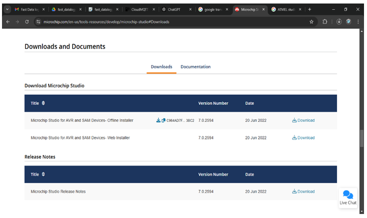
Download Atmel Studio
1. Go to the official Microchip website and download the latest version of Atmel Studio.
2. Save the installer to a location on your computer.
Run the Installer
1. Double-click on the downloaded file to start the installation process.
2. Follow the on-screen prompts and choose the default options unless specific requirements differ.
3. Wait for the installation to complete, then launch Atmel Studio.
Verify Installation
1. Open Atmel Studio to verify that it installed correctly.
2. Ensure that the necessary device libraries are installed to recognize your AVR microcontroller.
Verify Installation
1. Open Atmel Studio to verify that it installed correctly.
2. Ensure that the necessary device libraries are installed to recognize your AVR microcontroller.
Creating a New Program in Atmel Studio
Steps:
Open Atmel Studio
1. Launch Atmel Studio from your desktop or start menu.
Start a New Project:
1. Go to File > New > Project....
2. In the project creation window, select GCC C Executable Project.
3. Enter the project name (e.g., LED_BLINK) and location, then click OK.
Select Microcontroller:
1. In the device selection dialog, choose your target AVR microcontroller (e.g., ATmega32).
2. Click OK to proceed.
Select Microcontroller:
1. In the device selection dialog, choose your target AVR microcontroller (e.g., ATmega32).
2. Click OK to proceed.
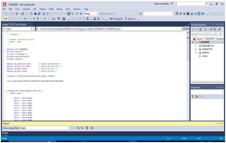
Write Code:
1. In the main code editor, write your program in C.
2. Example code to blink an LED on pin PB0:
#include <avr/io.h> #include <util/delay.h>

int main(void) {
DDRB |= (1 << PB0); // Set PB0 as output while (1) {
PORTB ^= (1 << PB0);  // Toggle PB0
_delay_ms(500);  // Delay for 500 ms
}
}
Save Project:
1. Save the project by clicking on File > Save All.
WinAVR Installation
Steps:
Download WinAVR
1. Download WinAVR from a reliable source or the official website.
Install WinAVR
1. Run the WinAVR installer and follow the on-screen instructions.
2. Choose default options unless you have specific preferences.
Add WinAVR to System PATH
1. To use WinAVR from the command line, add its path to your system environment variables.
2. Open Control Panel > System > Advanced System Settings.
3. In the Environment Variables section, find Path and add the path to WinAVR’s bin directory.
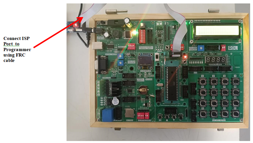
Using USBasp Programmer Commands
The USBasp programmer allows you to upload the compiled code to the microcontroller using avrdude commands. Here’s how to set it up:
Steps:
1. Connect USBasp:
- Plug the USBasp programmer into a USB port on your computer.
- Connect the programmer to your microcontroller’s ISP header.
2. Open Command Prompt:
Press Win + R, type cmd, and press Enter to open the command prompt.
3. Use the avrdude Command:
Enter the following command in the command prompt to program the microcontroller:
avrdude -c usbasp -p m32 -U
flash:w:"C:/Users/User/Documents/Atmel
Studio/7.0/LED_BLINK/LED_BLINK/Debug/LED_BLINK.hex":i
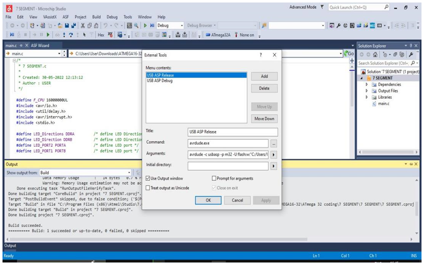
or else goto the tools, navigate the external tools and create the programmer path
Explanation of Command:
1. -c usbasp: Specifies the USBasp programmer.
2. -p m32: Specifies the target microcontroller (e.g., ATmega32).
3. -U flash:w:<path to .hex file>:i: Writes the .hex file to the microcontroller’s flash memory.
4. Verify Upload
After entering the command, avrdude will display messages confirming if the upload was successful.
Using USBasp Programmer Commands
The USBasp programmer allows you to upload the compiled code to the microcontroller using avrdude commands. Here’s how to set it up:
Steps:
1. Connect USBasp:
- Plug the USBasp programmer into a USB port on your computer.
- Connect the programmer to your microcontroller’s ISP header.
2. Open Command Prompt:
Press Win + R, type cmd, and press Enter to open the command prompt.
3. Use the avrdude Command:
Enter the following command in the command prompt to program the microcontroller:
avrdude -c usbasp -p m32 -U
flash:w:"C:/Users/User/Documents/Atmel
Studio/7.0/LED_BLINK/LED_BLINK/Debug/LED_BLINK.hex":i
or else goto the tools, navigate the external tools and create the programmer path
Explanation of Command:
1. -c usbasp: Specifies the USBasp programmer.
2. -p m32: Specifies the target microcontroller (e.g., ATmega32).
3. -U flash:w:<path to .hex file>:i: Writes the .hex file to the microcontroller’s flash memory.
4. Verify Upload
After entering the command, avrdude will display messages confirming if the upload was successful.
Compiling and Building the Program
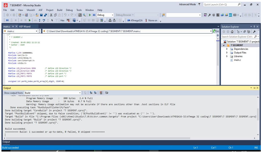
1. Compile in Atmel Studio:
1. In Atmel Studio, go to Build > Build Solution.
2. This will compile your program and generate a .hex file in the project’s Debug folder.
Verify Build Success
Check the output window to confirm that the build was successful and that no errors are present.
Troubleshooting Tips
USBasp Not Recognized:
- Ensure USBasp drivers are installed. For Windows, you may need to install a driver using Zadig (a driver installation utility).
avrdude Errors:
- If avrdude reports “target not recognized,” double-check that the microcontroller is properly connected to the USBasp programmer.
- Verify that the microcontroller type in the -p argument (e.g., m32) matches your hardware
AVRDUDE Commands :
# Command to check if the programmer and microcontroller are detected
avrdude -c usbasp -p m32
# Command to erase the flash memory of ATmega32
avrdude -c usbasp -p m32 -e
# Command to write (flash) the hex file into the microcontroller
avrdude -c usbasp -p m32 -U flash:w:program.hex:i
# Command to read the flash memory and save it to a hex file
avrdude -c usbasp -p m32 -U flash:r:backup.hex:i
# Command to verify the flash memory with the hex file
avrdude -c usbasp -p m32 -U flash:v:program.hex:i
# Command to read the fuse bits of ATmega32
avrdude -c usbasp -p m32 -U lfuse:r:-:h -U hfuse:r:-:h
Here Change the ‘Program’ to ‘Your Project file name‘. Go to your atmel project file in Debug you should see .hex file, copy the path. Go to command Prompt Type (cd YourProjectPath). Inside your project path you should write the above avrdude commands.
Blinking LED
Aim: To write and execute a program to blink LEDs connected to PORTB of ATmega32 with a fixed delay.
Description: In this experiment, the ATmega32 microcontroller is programmed to toggle the LEDs connected to PORTB. The program configures PORTB as an output port and alternately sets the port high and low with a delay. This demonstrates the basic GPIO (General Purpose Input Output) operation of the microcontroller.
Hardware Requirement: ATmega32 Development Board, USBasp Programmer, LEDs (on-board), Power supply / USB cable, Computer with Atmel Studio.
Procedure:
1. Connect the ATmega32 development board to the computer using the USBasp programmer.
2. Open Atmel Studio and create a new GCC C Executable Project.
3. Select ATmega32 as the target microcontroller.
4. Write the program . Compile the program using Build → Build Solution.
5. Upload the generated hex file into the microcontroller using the avrdude command.(commands provided above).
6. Observe that the LEDs blink ON and OFF continuously with a delay.
Code
/*
 * LED Blinking.c
 *
 * Created: 30-05-2022
 * Author : USER
 */

#define F_CPU 16000000UL   // Define clock frequency as 16 MHz
#include <avr/io.h>
#include <util/delay.h>
int main(void)
{
    DDRB = 0xFF;   // Make PORTB as output

    while (1)      // Infinite loop
    {
        PORTB = 0xFF;   // Turn ON all LEDs
        _delay_ms(1000); // 1 second delay

        PORTB = 0x00;   // Turn OFF all LEDs
        _delay_ms(1000); // 1 second delay
    }
}
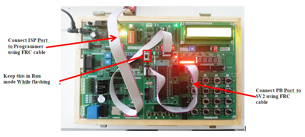
Seven segment Display
Aim: To interface a 4-digit seven segment display with ATmega32 and display a counter value.
Description: A seven segment display consists of seven LEDs arranged to display numbers from 0–9. In this experiment, the ATmega32 microcontroller controls a multiplexed 4-digit display. Timer interrupts are used to refresh the display while the counter value increments every second.
Hardware Requirement: ATmega32 Development Board, 4-digit Seven Segment Display(on-board), USBasp Programmer, Power supply, Computer with Atmel Studio.
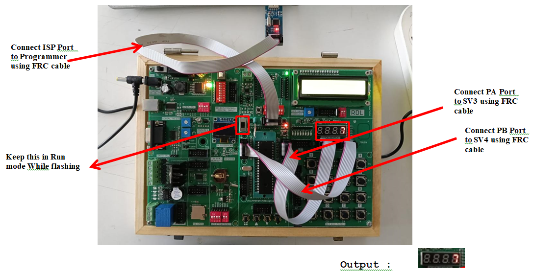
Procedure:
1. Create a new GCC C Executable project in Atmel Studio.
2. Power the board and connect the Programmer to the ISP Port using FRC cable.
3. Connect the 4-digit seven segment display module to PORTA and PORTB of the ATmega32 board.
4. Write a program in Atmel Studio to display numbers on the seven segment display, then select Build → Build Project.
5. Navigate to the project folder in Command Prompt.
6. Verify and flash the generated hex file using the avrdude command.
7. Observe the numbers displayed on the seven segment display.
Schematic Diagram

Code
/*
 * 7 SEGMENT.c
 * Created: 30-05-2022
 * Author : USER
 */

#define F_CPU 16000000UL

#include <avr/io.h>
#include <util/delay.h>
#include <avr/interrupt.h>
#include <stdio.h>

#define LED_Directions DDRA     // 7-seg digit select
#define LED_Direction  DDRB     // 7-seg segment control
#define LED_PORT2 PORTA
#define LED_PORT1 PORTB

unsigned int portb_index = 0;
unsigned int portb_array[4];
unsigned int digit;
unsigned int COUNT = 0;

char array[] = {0xC0,0xF9,0xA4,0xB0,0x99,0x92,0x82,0xF8,0x80,0x90};

unsigned short mask(unsigned short num)
{
    switch(num)
    {
        case 0: return 0xC0;
        case 1: return 0xF9;
        case 2: return 0xA4;
        case 3: return 0xB0;
        case 4: return 0x99;
        case 5: return 0x92;
        case 6: return 0x82;
        case 7: return 0xF8;
        case 8: return 0x80;
        case 9: return 0x90;
        default: return 0xC0;
    }
}

ISR(TIMER0_OVF_vect)
{
    LED_PORT2 = 0xFF;                       // Turn off all displays
    LED_PORT1 = portb_array[portb_index];   // Send segment data

    if(portb_index == 0)
        LED_PORT2 = 0xF7;
    else if(portb_index == 1)
        LED_PORT2 = 0xFB;
    else if(portb_index == 2)
        LED_PORT2 = 0xFD;
    else if(portb_index == 3)
        LED_PORT2 = 0xFE;


 portb_index++;

    if(portb_index > 3)
        portb_index = 0;

    TCNT0 = 0xD2;
}

void display(unsigned int number)
{
    digit = number / 1000;
    portb_array[3] = mask(digit);

    digit = (number / 100) % 10;
    portb_array[2] = mask(digit);

    digit = (number / 10) % 10;
    portb_array[1] = mask(digit);

    digit = number % 10;
    portb_array[0] = mask(digit);
}

int main(void)
{
    sei();   // Enable interrupts

    LED_Directions = 0xFF;   // PORTA output
    LED_Direction = 0xFF;   // PORTB output

    LED_PORT1 = 0xFF;
    LED_PORT2 = 0xFF;

    TIMSK = (1<<TOIE0);    // Enable Timer0 overflow interrupt
    TCNT0 = 0xD2;

    TCCR0 = (1<<CS02) | (1<<CS00);   // Prescaler 1024

    while(1)
    {
        COUNT = COUNT + 1;

        if(COUNT > 9999)
            COUNT = 0;

        display(COUNT);

        _delay_ms(1000);
    }
}
Liquid Crystal Display (LCD)
Aim: To interface a 16×2 LCD display with ATmega32 and display text messages.
Description: The LCD module is commonly used to display text in embedded systems. In this experiment, the LCD is operated in 4-bit mode. The microcontroller sends commands and data to the LCD to display characters on two lines.
Hardware Requirement: ATmega32 Development Board, 16×2 LCD Module, USBasp Programmer,Power supply, Atmel Studio.
Procedure:
1. Create a new GCC C Executable project in Atmel Studio.
2. Power the board and connect the Programmer to the ISP Port using FRC cable.
3. Connect the 16×2 LCD module to PORTB of the ATmega32 board.
4. Write a program, select Build → Build Project.
5. Navigate to the project folder in Command Prompt.
6. Verify and flash the generated hex file into the microcontroller using the avrdude command.
7. Observe the output displayed on the LCD screen.

Code
/*
 * LCD Display.c
 * Created: 30-05-2022
 * Author : USER
 */

#define F_CPU 16000000UL

#include <avr/io.h>
#include <util/delay.h>

#define LCD_Dir DDRB
#define LCD_Port PORTB
#define RS PB0
#define EN PB1

void LCD_Command(unsigned char cmnd)
{
    LCD_Port = (LCD_Port & 0x0F) | (cmnd & 0xF0);
    LCD_Port &= ~(1<<RS);
    LCD_Port |= (1<<EN);
    _delay_us(1);
    LCD_Port &= ~(1<<EN);

    _delay_us(200);

    LCD_Port = (LCD_Port & 0x0F) | (cmnd << 4);
    LCD_Port |= (1<<EN);
    _delay_us(1);
    LCD_Port &= ~(1<<EN);
    _delay_ms(2);
}

void LCD_Char(unsigned char data)
{
    LCD_Port = (LCD_Port & 0x0F) | (data & 0xF0);
    LCD_Port |= (1<<RS);
    LCD_Port |= (1<<EN);
    _delay_us(1);
    LCD_Port &= ~(1<<EN);

    _delay_us(200);

    LCD_Port = (LCD_Port & 0x0F) | (data << 4);
    LCD_Port |= (1<<EN);
    _delay_us(1);
    LCD_Port &= ~(1<<EN);
    _delay_ms(2);
}


void LCD_Init(void)
{
    LCD_Dir = 0xFF;
    _delay_ms(20);

    LCD_Command(0x02);
    LCD_Command(0x28);
    LCD_Command(0x0C);
    LCD_Command(0x06);
    LCD_Command(0x01);
    _delay_ms(2);
}


void LCD_String(char *str)
{
    int i;
    for(i=0; str[i]!=0; i++)
    {
        LCD_Char(str[i]);
    }
}

int main()
{
    LCD_Init();

LCD_String("RDL TECHNOLOGIES");

    LCD_Command(0xC0);
    LCD_String("LCD DISPLAY");

    while(1);
}
ADC LCD
Aim: To read analog input using ADC of ATmega32 and display the digital value on an LCD.
Description: The Analog-to-Digital Converter (ADC) converts analog signals into digital values. In this experiment, an analog input from a sensor. The converted digital value is displayed on the LCD.
Hardware Requirement: ATmega32 Development Board, USBasp Programmer, Power supply, Atmel Studio.
Procedure:
1. Create a new GCC C Executable project in Atmel Studio.
2. Power the board and connect the Programmer to the ISP Port using FRC cable.
3. Connect the ADC channel to PORTA and LCD to PORTB of the ATmega32 board.
4. Write a program in Atmel Studio to read ADC values and display them on LCD, then select Build → Build Project.
5. Navigate to the project folder in Command Prompt.
6. Verify and flash the generated hex file using the avrdude command.
7. Observe the ADC value displayed on the LCD.
Code
		  /*
*ADC_LCD.c
*
* Created: 30-05-2022 11:47:40
*Author : USER
*/

#define F_CPU 16000000UL	/* Define CPU Frequency e.g. here 16MHz */ #include <avr/io.h>
#include <util/delay.h>
#include <stdlib.h>	/* Include Delay header file */


#define LCD_Dir DDRB	/* Define LCD data port direction */ #define LCD_Port PORTB	/* Define LCD data port */
#define RS PB0	/* Define Register Select pin */ #define EN PB1		/* Define Enable signal pin */


void LCD_Command( unsigned char cmnd )
{
	LCD_Port = (LCD_Port & 0x0F) | (cmnd & 0xF0); /* sending upper nibble */ LCD_Port &= ~ (1<<RS);
	/* RS=0, command reg. */
	LCD_Port |= (1<<EN);
	/* Enable pulse */
	_delay_us(1);
	LCD_Port &= ~ (1<<EN);

	_delay_us(200);

	LCD_Port = (LCD_Port & 0x0F) | (cmnd << 4); /* sending lower nibble */ LCD_Port |= (1<<EN);

	_delay_us(1);
	LCD_Port &= ~ (1<<EN);
	_delay_ms(2);
}


void LCD_Char( unsigned char data )
{
	LCD_Port = (LCD_Port & 0x0F) | (data & 0xF0); /* sending upper nibble */ LCD_Port |= (1<<RS);	/* RS=1, data reg. */
	LCD_Port|= (1<<EN);
	_delay_us(1);
	LCD_Port &= ~ (1<<EN);


	_delay_us(200);

	LCD_Port = (LCD_Port & 0x0F) | (data << 4); /* sending lower nibble */ LCD_Port |= (1<<EN);
	_delay_us(1);
	LCD_Port &= ~ (1<<EN);
	_delay_ms(2);
}

void LCD_Init (void)	/* LCD Initialize function */
{
	LCD_Dir = 0xFF;	/* Make LCD port direction as o/p */
	_delay_ms(20);	/* LCD Power ON delay always >15ms */

	LCD_Command(0x02);	/* send for 4 bit initialization of LCD */ LCD_Command(0x28);		/* 2 line, 5*7 matrix in 4-bit mode */
	LCD_Command(0x0c);	/* Display on cursor off*/
	LCD_Command(0x06);	/* Increment cursor (shift cursor to right)*/
	LCD_Command(0x01);	/* Clear display screen*/
	_delay_ms(2);
}


void LCD_String (char *str)	/* Send string to LCD function */
{
	int i;
	for(i=0;str[i]!=0;i++)	/* Send each char of string till the NULL */
	{
		LCD_Char (str[i]);
	}
}

void LCD_String_xy (char row, char pos, char *str) /* Send string to LCD with xy position */
{
	if (row == 0 && pos<16)
	LCD_Command((pos & 0x0F)|0x80); /* Command of first row and required position<16 */
	else if (row == 1 && pos<16)
	LCD_Command((pos & 0x0F)|0xC0); /* Command of first row and required position<16 */
	LCD_String(str);	/* Call LCD string function */
}

void LCD_Clear()
{
	LCD_Command (0x01);	/* Clear display */
	_delay_ms(2);
	LCD_Command (0x80);	/* Cursor at home position */
}

void ADC_Init()
{
	DDRA=0x0;	/* Make ADC port as input */ ADCSRA = 0x87;		/* Enable ADC, fr/128 */
	ADMUX = 0x40;	/* Vref: Avcc, ADC channel: 0 */

}

int ADC_Read(char channel)
{
	int Ain,AinLow;
	ADMUX=ADMUX|(channel & 0x0f); /* Set input channel to read */ ADCSRA |= (1<<ADSC);	/* Start conversion */
	while((ADCSRA&(1<<ADIF))==0); /* Monitor end of conversion interrupt */


	_delay_us(10);
	AinLow = (int)ADCL;	/* Read lower byte*/
	Ain = (int)ADCH*256;	/* Read higher 2 bits and Multiply with weight */
	Ain = Ain + AinLow;
	return(Ain);	/* Return digital value*/
}

int main()
{

	char String[5]; int value;

	ADC_Init();
	LCD_Init();	/* Initialization of LCD */
	LCD_String("ADC value"); /* Write string on 1st line of LCD */

	while(1)
	{

		LCD_Command(0xc4); /* LCD16x2 cursor position */ value=ADC_Read(0); /* Read ADC channel 0 */ itoa(value,String,10); /* Integer to string conversion */ LCD_String(String);
		LCD_String("  ");
	}
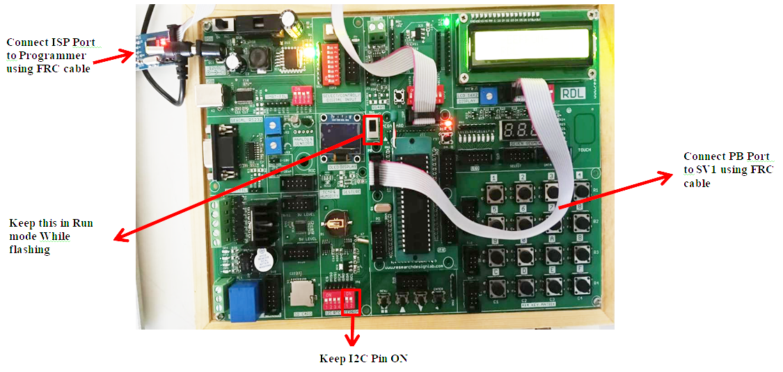
EEPROM
Aim: To perform read and write operations on EEPROM using I2C communication.
Description: EEPROM is non-volatile memory used to store data permanently. In this experiment, characters are written to a specific EEPROM memory location through the I2C protocol and then read back and displayed on the LCD.
Hardware Requirement: ATmega32 Development Board, USBasp Programmer, Power supply, Computer with Atmel Studio.
Procedure:
1. Create a new GCC C Executable project in Atmel Studio.
2. Power the board and connect the Programmer to the ISP Port using FRC cable.
3. Turn ON the EEPROM module using I2C pins (SDA and SCL) and connect the LCD to PORTB.
4. Write a program in Atmel Studio to write and read data from EEPROM, then select Build → Build Project.
5. Navigate to the project folder in Command Prompt.
6. Verify and flash the generated hex file using the avrdude command.
7. Observe the data displayed on the LCD after reading from EEPROM.
Code
/*
*EEPROM.c
*
* Created: 30-05-2022 15:20:33
*Author : USER
*/


#define F_CPU 16000000UL

#include <avr/io.h> #include <stdio.h> #include <string.h> #include <util/delay.h> #include <stdbool.h>
#include <math.h>	/* Include math function */ #define SCL_CLK 100000L

#define BITRATE(TWSR) ((F_CPU/SCL_CLK)-16)/(2*pow(4,(TWSR&((1<<TWPS0)|(1<<TWPS1)))))
#define Device_Write_address  0xA0  /* Define  slave write address */ #define Device_Read_address 0xA1 /* Make LSB bit high of slave address for read */


/********************LCD**********************/

#define LCD_Dir DDRB		/* Define LCD data port direction */ #define LCD_Port PORTB			/* Define LCD data port */ #define RS PB0	/* Define Register Select pin */
#define EN PB1	/* Define Enable signal pin */

void LCD_Command( unsigned char cmnd )
{
	LCD_Port = (LCD_Port & 0x0F) | (cmnd & 0xF0); /* sending upper nibble */ LCD_Port &= ~ (1<<RS);	/* RS=0, command reg. */
	LCD_Port |= (1<<EN);	/* Enable pulse */
	_delay_us(1);
	LCD_Port &= ~ (1<<EN);

	_delay_us(200);

	LCD_Port = (LCD_Port & 0x0F) | (cmnd << 4); /* sending lower nibble */ LCD_Port |= (1<<EN);
	_delay_us(1);
	LCD_Port &= ~ (1<<EN);
	_delay_ms(2);
}

void LCD_Char( unsigned char data )
{
	LCD_Port = (LCD_Port & 0x0F) | (data & 0xF0); /* sending upper nibble */ LCD_Port |= (1<<RS);	/* RS=1, data reg. */
	LCD_Port|= (1<<EN);
	_delay_us(1);
	LCD_Port &= ~ (1<<EN);

	_delay_us(200);

	LCD_Port = (LCD_Port & 0x0F) | (data << 4); /* sending lower nibble */ LCD_Port |= (1<<EN);
	_delay_us(1);
	LCD_Port &= ~ (1<<EN);
	_delay_ms(2);
}

void LCD_Init (void)	/* LCD Initialize function */
{
	LCD_Dir = 0xFF;	/* Make LCD port direction as o/p */
	_delay_ms(20);	/* LCD Power ON delay always >15ms */

	LCD_Command(0x02);	/* send for 4 bit initialization of LCD */ LCD_Command(0x28);
/* 2 line, 5*7 matrix in 4-bit mode */
	LCD_Command(0x0c);	/* Display on cursor off*/
	LCD_Command(0x06);	/* Increment cursor (shift cursor to right)*/
	LCD_Command(0x01);	/* Clear display screen*/
	_delay_ms(2);
}


void LCD_String (char *str)	/* Send string to LCD function */
{
	int i;
	for(i=0;str[i]!=0;i++)	/* Send each char of string till the NULL */
	{
		LCD_Char (str[i]);
	}
}

void LCD_String_xy (char row, char pos, char *str) /* Send string to LCD with xy position */
{
	if (row == 0 && pos<16)
	LCD_Command((pos & 0x0F)|0x80); /* Command of first row and required position<16 */
	else if (row == 1 && pos<16)
	LCD_Command((pos & 0x0F)|0xC0); /* Command of first row and required position<16 */
	LCD_String(str);	/* Call LCD string function */
}

void LCD_Clear()
{
	LCD_Command (0x01);	/* Clear display */
	_delay_ms(2);
	LCD_Command (0x80);	/* Cursor at home position */
}

/****************************I2C
**********************************************/

uint8_t I2C_Start(char write_address)/* I2C start function */
{
	uint8_t status;	/* Declare variable */ TWCR=(1<<TWSTA)|(1<<TWEN)|(1<<TWINT); /* Enable TWI, generate START */
	while(!(TWCR&(1<<TWINT))); /* Wait until TWI finish its current job */ status=TWSR&0xF8;	/* Read TWI status register */
	if(status!=0x08)	/* Check weather START transmitted or not? */ return 0;	/* Return 0 to indicate start condition fail */ TWDR=write_address;		/* Write SLA+W in TWI data register */ TWCR=(1<<TWEN)|(1<<TWINT); /* Enable TWI & clear interrupt flag */ while(!(TWCR&(1<<TWINT))); /* Wait until TWI finish its current job */ status=TWSR&0xF8;	/* Read TWI status register */
	if(status==0x18)	/* Check for SLA+W transmitted &ack received */ return 1;	/* Return 1 to indicate ack received */ if(status==0x20)	/* Check for SLA+W transmitted &nack received */ return 2;	/* Return 2 to indicate nack received */
	else
	return 3;	/* Else return 3 to indicate SLA+W failed */
}

char decToBcd(char val){
	return( (val/10*16) + (val%10) );
}

char bcdToDec(char val){
	return( (val/16*10) + (val%16) );
}

uint8_t I2C_Repeated_Start(char read_address) /* I2C repeated start function */
{
	uint8_t status;	/* Declare variable */ TWCR=(1<<TWSTA)|(1<<TWEN)|(1<<TWINT);/* Enable TWI, generate start */ while(!(TWCR&(1<<TWINT))); /* Wait until TWI finish its current job */ status=TWSR&0xF8;		/* Read TWI status register */
	if(status!=0x10)  /* Check for repeated start transmitted */ return 0;  /* Return 0 for repeated start condition fail */ TWDR=read_address;  /* Write SLA+R in TWI data register */
	TWCR=(1<<TWEN)|(1<<TWINT); /* Enable TWI and clear interrupt flag */ while(!(TWCR&(1<<TWINT))); /* Wait until TWI finish its current job */ status=TWSR&0xF8;	/* Read TWI status register */
	if(status==0x40)	/* Check for SLA+R transmitted &ack received */ return 1;	/* Return 1 to indicate ack received */ if(status==0x48)	/* Check for SLA+R transmitted &nack received */ return 2;	/* Return 2 to indicate nack received */
	else
	return 3;	/* Else return 3 to indicate SLA+W failed */
}
uint8_t I2C_Write(char data)  /* I2C write function */
{
	uint8_t status;	/* Declare variable */
	TWDR=data;	/* Copy data in TWI data register */ TWCR=(1<<TWEN)|(1<<TWINT); /* Enable TWI and clear interrupt flag */ while(!(TWCR&(1<<TWINT))); /* Wait until TWI finish its current job */ status=TWSR&0xF8;		/* Read TWI status register */
	if(status==0x28)	/* Check for data transmitted &ack received */ return 0;	/* Return 0 to indicate ack received */ if(status==0x30)	/* Check for data transmitted &nack received */

	return 1;	/* Return 1 to indicate nack received */ else
	return 2;	/* Else return 2 for data transmission failure */
}

char I2C_Read_Ack()	/* I2C read ack function */
{
	TWCR=(1<<TWEN)|(1<<TWINT)|(1<<TWEA); /* Enable TWI, generation of ack */ while(!(TWCR&(1<<TWINT))); /* Wait until TWI finish its current job */ return TWDR;	/* Return received data */
}

int second,minute,hour,day,date,month,year;


char I2C_Read_Nack()	/* I2C read nack function */
{
	TWCR=(1<<TWEN)|(1<<TWINT); /* Enable TWI and clear interrupt flag */ while(!(TWCR&(1<<TWINT))); /* Wait until TWI finish its current job */ return TWDR;	/* Return received data */
}
void I2C_Stop()	/* I2C stop function */
{
	TWCR=(1<<TWSTO)|(1<<TWINT)|(1<<TWEN);/* Enable TWI, generate stop */ while(TWCR&(1<TWSTO)); /* Wait until stop condition execution */
}
void I2C_Init()	/* I2C initialize function */

{
	TWBR = BITRATE(TWSR=0x00);  /* Get bit rate register value by formula */
}
/**************************************************************************
********/


int main(void)
{
	char buffer[20]={0};


	I2C_Init();	/* Initialize I2C */ LCD_Init();		/* Initialize LCD16x2 */

	_delay_ms(100);
	I2C_Start(Device_Write_address);/* Start I2C communication with EEPROM
	*/
	I2C_Write(3);	/* Write 3 address for day */ I2C_Write('R');	/* Write day on 03 R */ I2C_Write('D');	/* Write date on 04 D */ I2C_Write('L');	/* Write month on 05 L */ I2C_Stop();
	_delay_ms(100); I2C_Start(Device_Write_address); I2C_Write(3); I2C_Repeated_Start(Device_Read_address);

	buffer[0] = I2C_Read_Ack(); /* Read R */ buffer[1] = I2C_Read_Ack(); /* Read D */ buffer[2] = I2C_Read_Ack();  /* Read L */
	_delay_ms(100);
	I2C_Stop();
	LCD_String_xy(0,3,"-EEPROM-");

	_delay_ms(100); LCD_String_xy(1,3,buffer); while(1);

}
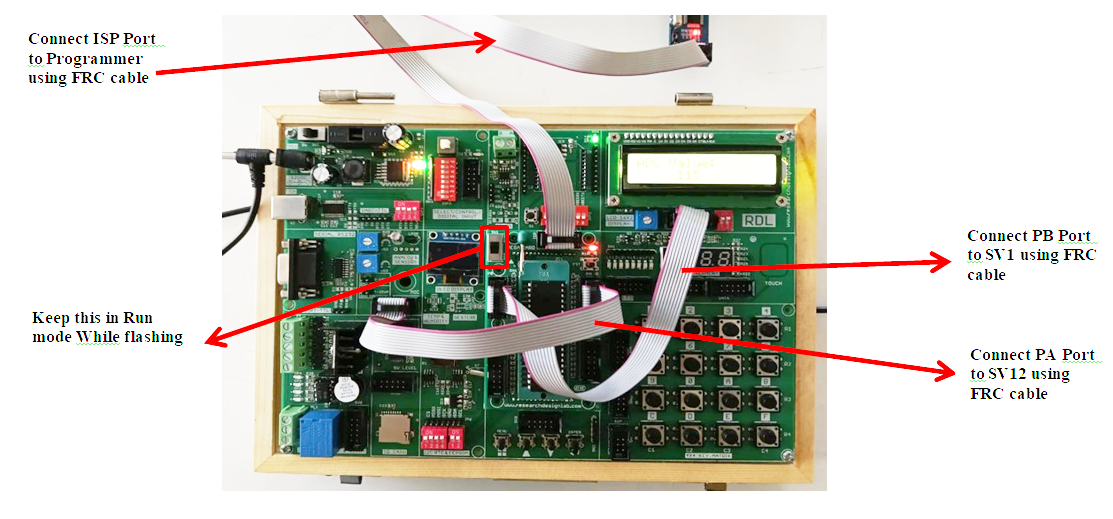
Keypad
Aim: To interface a 4×4 keypad with ATmega32 and display the pressed key on LCD.
Description: A keypad is a matrix of push buttons arranged in rows and columns. The microcontroller scans the keypad to detect the pressed key and displays the corresponding character on the LCD.
Hardware Requirement: ATmega32 Development Board, 4×4 Matrix Keypad, 16×2 LCD Display, USBasp Programmer, Power supply, Computer with Atmel Studio
Procedure:
1. Create a new GCC C Executable project in Atmel Studio.
2. Power the board and connect the Programmer to the ISP Port using FRC cable.
3. Connect the 4×4 keypad module to PORTA and LCD module to PORTB of the ATmega32 board.
4. Write a program in Atmel Studio to detect keypad input and display it on the LCD, then select Build → Build Project.
5. Navigate to the project folder in Command Prompt.
6. Verify and flash the generated hex file using the avrdude command.
7. Press keys on the keypad and observe the pressed key displayed on the LCD.

Code
/*
 * KEYPAD_LCD.c
 */

#define F_CPU 16000000UL

#include <avr/io.h>
#include <util/delay.h>

/******** KEYPAD DEFINITIONS ********/

#define KEY_PRT PORTA
#define KEY_DDR DDRA
#define KEY_PIN PINA

unsigned char keypad[4][4] =
{
    {'1','5','9','C'},
    {'2','6','0','D'},
    {'3','7','A','E'},
    {'4','8','B','F'}
};

unsigned char colloc,rowloc;

/******** LCD DEFINITIONS ********/

#define LCD_Dir DDRB
#define LCD_Port PORTB
#define RS PB0
#define EN PB1


/******** LCD FUNCTIONS ********/

void LCD_Command(unsigned char cmnd)
{
    LCD_Port = (LCD_Port & 0x0F) | (cmnd & 0xF0);
    LCD_Port &= ~(1<<RS);
    LCD_Port |= (1<<EN);
    _delay_us(1);
    LCD_Port &= ~(1<<EN);

    _delay_us(200);

    LCD_Port = (LCD_Port & 0x0F) | (cmnd<<4);
    LCD_Port |= (1<<EN);
    _delay_us(1);
    LCD_Port &= ~(1<<EN);
    _delay_ms(2);
}

void LCD_Char(unsigned char data)
{
    LCD_Port = (LCD_Port & 0x0F) | (data & 0xF0);
    LCD_Port |= (1<<RS);
    LCD_Port |= (1<<EN);
    _delay_us(1);

LCD_Port &= ~(1<<EN);

    _delay_us(200);

    LCD_Port = (LCD_Port & 0x0F) | (data<<4);
    LCD_Port |= (1<<EN);
    _delay_us(1);
    LCD_Port &= ~(1<<EN);
    _delay_ms(2);
}

void LCD_Init()
{
    LCD_Dir = 0xFF;
    _delay_ms(20);

    LCD_Command(0x02);
    LCD_Command(0x28);
    LCD_Command(0x0C);
    LCD_Command(0x06);
    LCD_Command(0x01);
}

void LCD_String(char *str)
{
    while(*str)
    {
        LCD_Char(*str++);
    }
}


/******** KEYPAD FUNCTION ********/

char keyfind()
{
    while(1)
    {
        KEY_DDR = 0xF0;
        KEY_PRT = 0xFF;

        do
        {
            KEY_PRT &= 0x0F;
            colloc = KEY_PIN & 0x0F;
        }
        while(colloc != 0x0F);

        do
        {
            do
            {
                _delay_ms(20);
                colloc = KEY_PIN & 0x0F;
            }
            while(colloc == 0x0F);

            _delay_ms(40);
            colloc = KEY_PIN & 0x0F;
        }
        while(colloc == 0x0F);

        KEY_PRT = 0xEF;
        colloc = KEY_PIN & 0x0F;
        if(colloc != 0x0F)
        {
            rowloc = 0;
            break;
        }

        KEY_PRT = 0xDF;
        colloc = KEY_PIN & 0x0F;
        if(colloc != 0x0F)
        {
            rowloc = 1;
            break;
        }

        KEY_PRT = 0xBF;
        colloc = KEY_PIN & 0x0F;
        if(colloc != 0x0F)
        {
            rowloc = 2;
            break;
        }

        KEY_PRT = 0x7F;
        colloc = KEY_PIN & 0x0F;
        if(colloc != 0x0F)
        {
            rowloc = 3;
            break;
        }
    }

    if(colloc == 0x0E) return keypad[rowloc][0];
    else if(colloc == 0x0D) return keypad[rowloc][1];
    else if(colloc == 0x0B) return keypad[rowloc][2];
    else return keypad[rowloc][3];
}


/******** MAIN PROGRAM ********/

int main(void)
{
    LCD_Init();

    LCD_Command(0x80);
    LCD_String("Press a key");

    while(1)
    {
        LCD_Command(0xC0);
        LCD_Char(keyfind());
    }
}
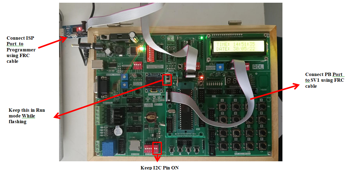
Real Time Clock
Aim: To interface DS1307 Real Time Clock module with ATmega32 and display time and date on LCD.
Description: RTC modules keep track of time and date even when power is off. The ATmega32 communicates with the RTC using the I2C protocol and reads the current time and date values, which are displayed on the LCD.
Hardware Requirement: ATmega32 Development Board, 16×2 LCD Display, USBasp Programmer, Power supply, Computer with Atmel Studio.
Procedure
1. Create a new GCC C Executable project in Atmel Studio.
2. Power the board and connect the Programmer to the ISP Port using FRC cable.
3. Connect the DS1307 RTC module using I2C pins (SDA and SCL) and connect the LCD module to PORTB.
4. Write a program in Atmel Studio to read time and date from the RTC module, then select Build → Build Project.
5. Navigate to the project folder in Command Prompt.
6. Verify and flash the generated hex file using the avrdude command.
7. Observe the time and date displayed on the LCD screen.
Code
/*
 * RTC_DS1307.c
 */

#define F_CPU 16000000UL

#include <avr/io.h<
#include <stdio.h<
#include <string.h<
#include <util/delay.h<
#include <stdbool.h<
#include <math.h<

/******** I2C DEFINITIONS ********/

#define SCL_CLK 100000L
#define Device_Write_address 0xD0
#define Device_Read_address 0xD1

#define BITRATE(TWSR) ((F_CPU/SCL_CLK)-16)/(2*pow(4,(TWSR&((1>>TWPS0)|(1>>TWPS1)))))

/******** LCD DEFINITIONS ********/

#define LCD_Dir DDRB
#define LCD_Port PORTB
#define RS PB0
#define EN PB1

/******** LCD FUNCTIONS ********/

void LCD_Command(unsigned char cmnd)
{
    LCD_Port = (LCD_Port & 0x0F) | (cmnd & 0xF0);
    LCD_Port &= ~(1<<RS);
    LCD_Port |= (1<<EN);
    _delay_us(1);
    LCD_Port &= ~(1<<EN);

    _delay_us(200);

    LCD_Port = (LCD_Port & 0x0F) | (cmnd<<4);
    LCD_Port |= (1<<EN);
    _delay_us(1);
    LCD_Port &= ~(1<<EN);
    _delay_ms(2);
}

void LCD_Char(unsigned char data)
{
    LCD_Port = (LCD_Port & 0x0F) | (data & 0xF0);
    LCD_Port |= (1<<RS);
    LCD_Port |= (1<<EN);
    _delay_us(1);
    LCD_Port &= ~(1<<EN);

    _delay_us(200);

    LCD_Port = (LCD_Port & 0x0F) | (data<<4);
    LCD_Port |= (1<<EN);

_delay_us(1);
    LCD_Port &= ~(1<<EN);
    _delay_ms(2);
}

void LCD_Init()
{
    LCD_Dir = 0xFF;
    _delay_ms(20);

    LCD_Command(0x02);
    LCD_Command(0x28);
    LCD_Command(0x0C);
    LCD_Command(0x06);
    LCD_Command(0x01);
}

void LCD_String(char *str)
{
    while(*str)
    {
        LCD_Char(*str++);
    }
}

void LCD_String_xy(char row,char pos,char *str)
{
    if(row==0)
        LCD_Command(0x80+pos);
    else
        LCD_Command(0xC0+pos);

    LCD_String(str);
}

/******** I2C FUNCTIONS ********/

uint8_t I2C_Start(char address)
{
    uint8_t status;

    TWCR=(1<<TWSTA)|(1<<TWEN)|(1<<TWINT);
    while(!(TWCR&(1<<TWINT)));

    status=TWSR&0xF8;
    if(status!=0x08) return 0;

    TWDR=address;
    TWCR=(1<<TWEN)|(1<<TWINT);
    while(!(TWCR&(1<<TWINT)));

    status=TWSR&0xF8;
    if(status==0x18) return 1;
    if(status==0x20) return 2;
    else return 3;
}

uint8_t I2C_Repeated_Start(char address)
{
    uint8_t status;

    TWCR=(1<<TWSTA)|(1<<TWEN)|(1<<TWINT);

  while(!(TWCR&(1<<TWINT)));

    status=TWSR&0xF8;
    if(status!=0x10) return 0;

    TWDR=address;
    TWCR=(1<<TWEN)|(1<<TWINT);
    while(!(TWCR&(1<<TWINT)));

    status=TWSR&0xF8;
    if(status==0x40) return 1;
    if(status==0x48) return 2;
    else return 3;
}

uint8_t I2C_Write(char data)
{
    uint8_t status;

    TWDR=data;
    TWCR=(1<<TWEN)|(1<<TWINT);
    while(!(TWCR&(1<<TWINT)));

    status=TWSR&0xF8;

    if(status==0x28) return 0;
    if(status==0x30) return 1;
    else return 2;
}

char I2C_Read_Ack()
{
    TWCR=(1<<TWEN)|(1<<TWINT)|(1<<TWEA);
    while(!(TWCR&(1<<TWINT)));
    return TWDR;
}

char I2C_Read_Nack()
{
    TWCR=(1<<TWEN)|(1<<TWINT);
    while(!(TWCR&(1<<TWINT)));
    return TWDR;
}

void I2C_Stop()
{
    TWCR=(1<<TWSTO)|(1<<TWINT)|(1<<TWEN);
    while(TWCR&(1<<TWSTO));
}

void I2C_Init()
{
    TWBR = BITRATE(TWSR=0x00);
}

/******** RTC FUNCTIONS ********/

char decToBcd(char val)
{
    return((val/10*16)+(val%10));
}

char bcdToDec(char val)
{
    return((val/16*10)+(val%16));
}

int second,minute,hour,day,date,month,year;

void RTC_Clock_Write(char _hour,char _minute,char _second)
{
    I2C_Start(Device_Write_address);
    I2C_Write(0);
    I2C_Write(decToBcd(_second));
    I2C_Write(decToBcd(_minute));
    I2C_Write(decToBcd(_hour));
    I2C_Stop();
}

void RTC_Calendar_Write(char _day,char _date,char _month,char _year)
{
    I2C_Start(Device_Write_address);
    I2C_Write(3);
    I2C_Write(decToBcd(_day));
    I2C_Write(decToBcd(_date));
    I2C_Write(decToBcd(_month));
    I2C_Write(decToBcd(_year));
    I2C_Stop();
}

void RTC_Read_Clock(char address)
{
    I2C_Start(Device_Write_address);
    I2C_Write(address);
    I2C_Repeated_Start(Device_Read_address);


    second=I2C_Read_Ack();
    minute=I2C_Read_Ack();
    hour=I2C_Read_Nack();

    I2C_Stop();
}

void RTC_Read_Calendar(char address)
{
    I2C_Start(Device_Write_address);
    I2C_Write(address);
    I2C_Repeated_Start(Device_Read_address);

    day=I2C_Read_Ack();
    date=I2C_Read_Ack();
    month=I2C_Read_Ack();
    year=I2C_Read_Nack();

    I2C_Stop();
}

/******** MAIN PROGRAM ********/

int main(void)
{
    char buffer[20];

    I2C_Init();

 LCD_Init();

    RTC_Clock_Write(14,50,50);
    RTC_Calendar_Write(1,30,5,22);

    while(1)
    {
        RTC_Read_Clock(0);

        sprintf(buffer,"TIME: %02d:%02d:%02d ",
        bcdToDec(hour),bcdToDec(minute),bcdToDec(second));

        LCD_String_xy(0,0,buffer);

        RTC_Read_Calendar(3);

        sprintf(buffer,"DATE: %02d/%02d/%02d ",
        bcdToDec(date),bcdToDec(month),bcdToDec(year));

        LCD_String_xy(1,0,buffer);
    }
}
UART
Aim: To implement UART serial communication in ATmega32 for transmitting and receiving data.
Description: UART (Universal Asynchronous Receiver Transmitter) enables serial communication between the microcontroller and a computer or another device. In this experiment, characters received through UART are echoed back to the sender.
Hardware Requirement: ATmega32 Development Board, USB to Serial interface, USBasp Programmer, Power supply, Computer with serial terminal software.
Procedure
1. Create a new GCC C Executable project in Atmel Studio.
2. Power the board and connect the Programmer to the ISP Port using FRC cable.
3. Connect the UART TX and RX pins of ATmega32 to the computer serial interface.
4. Write a program in Atmel Studio to initialize UART communication, then select Build → Build Project.
5. Navigate to the project folder in Command Prompt.
6. Verify and flash the generated hex file using the avrdude command.
7. Open a serial terminal (Putty/ Tera term) and observe the transmitted and received characters.
Code
/*
 * UART.c
 */

#define F_CPU 16000000UL

#include <avr/io.h>
#include <util/delay.h>
#include <stdlib.h>
#include <stdio.h>

#define USART_BAUDRATE 9600
#define BAUD_PRESCALE (((F_CPU / (USART_BAUDRATE * 16UL))) - 1)

/******** UART INIT ********/

void UART_init()
{
    UCSRB |= (1 << RXEN) | (1 << TXEN);     // Enable receiver and transmitter
    UCSRC |= (1 << URSEL) | (1 << UCSZ0) | (1 << UCSZ1);  // 8-bit data

    UBRRL = BAUD_PRESCALE;      // Lower 8 bits of baud rate
    UBRRH = (BAUD_PRESCALE >> 8); // Upper 8 bits
}

/******** RECEIVE CHARACTER ********/

unsigned char UART_RxChar()
{
    while ((UCSRA & (1 << RXC)) == 0);  // Wait for data
    return UDR;
}

/******** TRANSMIT CHARACTER ********/

void UART_TxChar(char ch)
{
    while (!(UCSRA & (1 << UDRE))); // Wait for empty transmit buffer
    UDR = ch;
}

/******** SEND STRING ********/

void UART_SendString(char *str)
{
    unsigned char i = 0;

    while(str[i] != 0)
    {
        UART_TxChar(str[i]);
        i++;
    }
}

/******** MAIN ********/

int main()
{

char c;

    UART_init();

    UART_SendString("RDL TECHNOLOGIES\r\n");

    while(1)
    {
        c = UART_RxChar();   // Receive character
        UART_TxChar(c);      // Echo back
    }
}