


Customers who bought this product also commonly purchased the following combination of items.
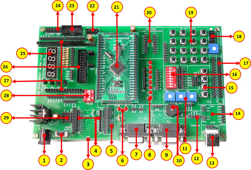
- This Item: ARM Development Board-LPC2129 With CAN Protocol
-
dsPIC Development Board
-
PIC Development Board
-
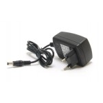
12V-2A DC Adapter
-
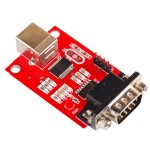
USB To RS232 Converter
-
-
Out of stock
-
Out of stock
-
Out of stock
-
Out of stock


Questions:
-
0voteA:
Dear Sir,
Please use the Keil ID4 complier to program LPC2148
Posted by on Saturday, 26 September 2015
-
0voteA:
Dear Sir,
You cannot program through serial port , you need touse Mini USB cable for programming purpose,
Kindly download the driver from below given link,
http://www.ftdichip.com/Drivers/VCP.htm
Also refer the below video link,
https://youtu.be/eyoey66EU9wPosted by on Friday, 21 August 2015
-
0voteA:
Dear Customer
Kindly download the driver from below given link,
http://www.ftdichip.com/Drivers/VCP.htm
Also refer the below video link,
https://youtu.be/eyoey66EU9w
Posted by on Friday, 21 August 2015
-
0voteA:
Dear Sir,
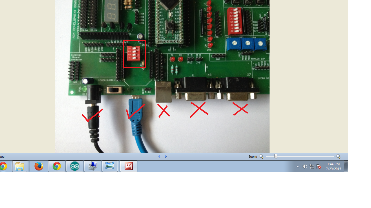
Please go through the below image, and follow the steps
1.Connect the MINI USB , make sure DIP switch is ON :
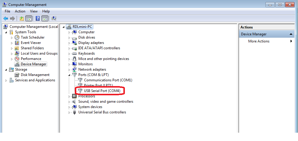
2.Go-To device manager check the comport selcted for ARM Development board mini USB:
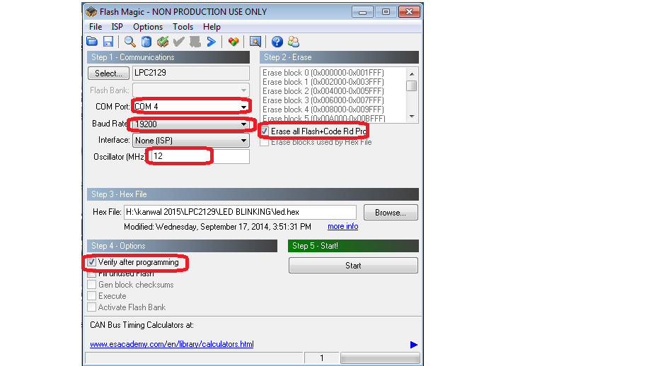
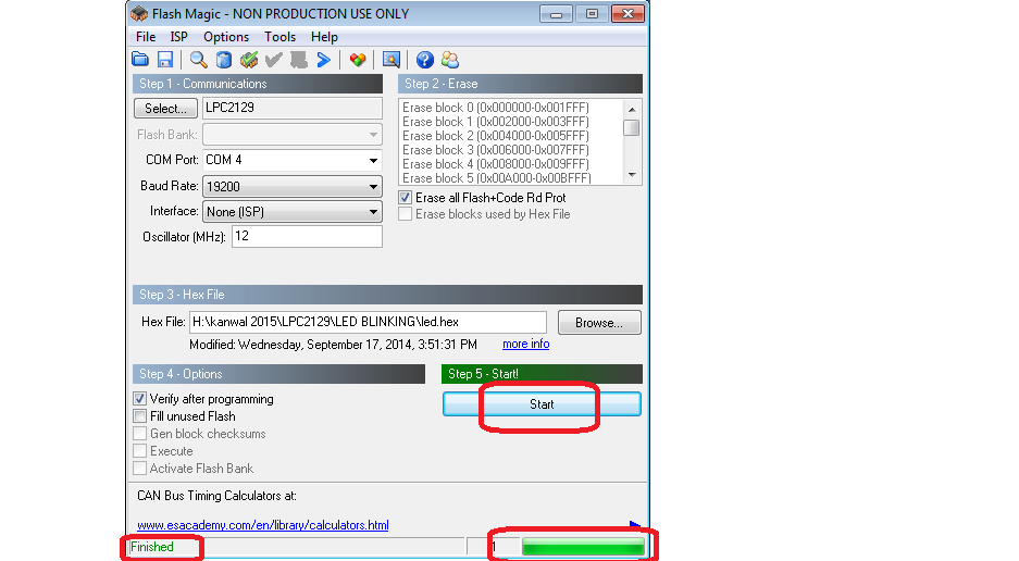
3.Open Flash Magic tool, select the appropriate COM port, set the Baud rate to less than or equal to 38400 bps, select device as LPC2148, interface as 'None (ISP)' and oscillator frequency as 12MHz.Click on 'Verify after programming' :
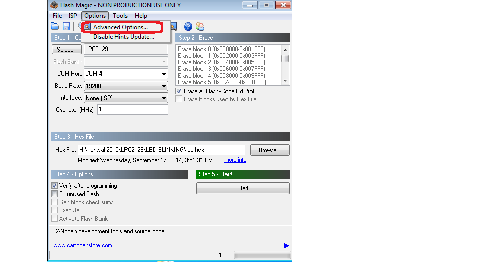
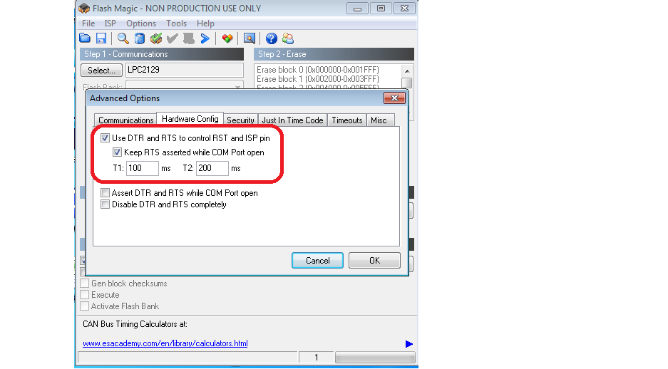
4:In Auto mode under the 'Options' tab select 'Advanced options'. In this under 'Hardware Config' tab make sure the options 'Use DTR and RTS to control RTS and P0.14' and 'Keep RTS asserted while COM port open' are checked. The values of T1 and T2 are set to 100ms and 200ms by default.
 5:Browse the HEX File :
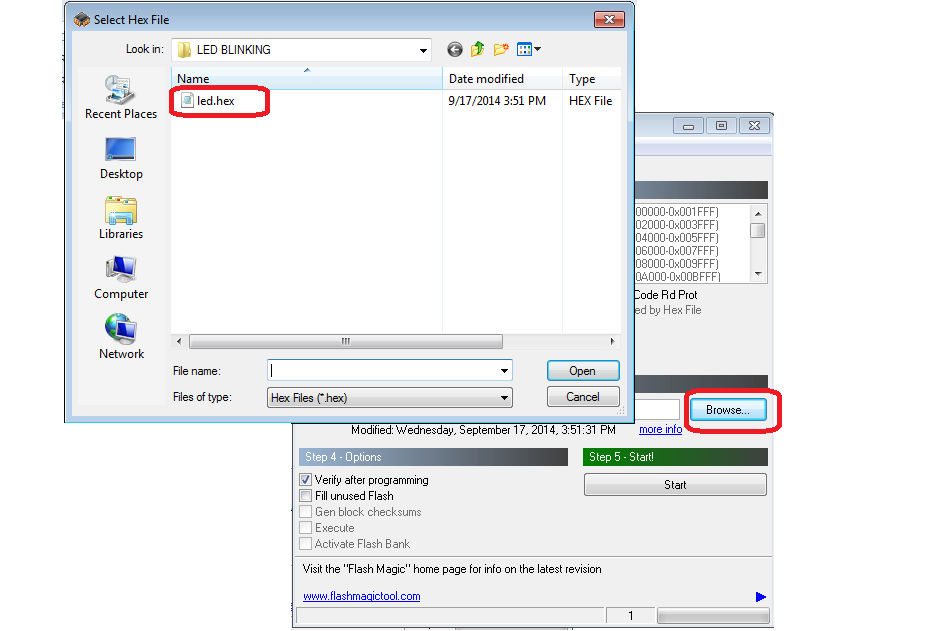
6:Click on start button :
 Posted by on Thursday, 20 August 2015