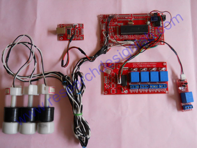
Smart Home Using Matlab GUI Block Diagram: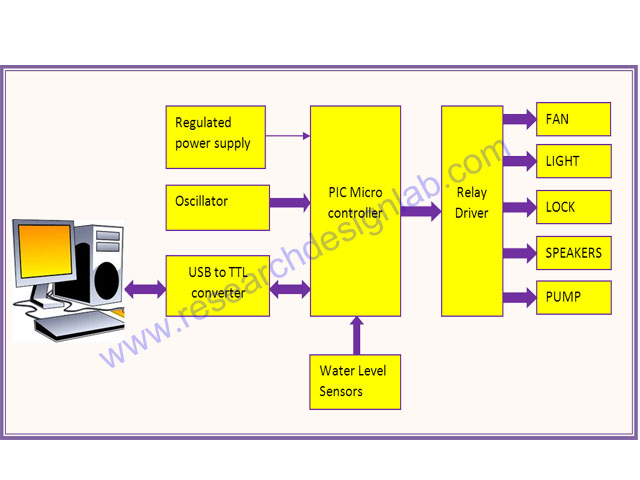
Smart Home Using Matlab GUI Working Principle:
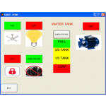
The microcontroller/processor is used to monitor and control the devices. An embedded c program is pre written into the microcontroller/processor which is programmed according to our need. The microcontroller/processor is then interfaced with the relays and the necessary water level sensors. Matlab will send a serial data to the microcontroller/processor via the serial interface. The microcontroller/processor replies if necessary and does the task assigned to it. The part of Matlab GUI is solely to provide user interface which when interrupted sends data to microcontroller/processor.
Controller:
Smart Home Using Matlab GUI Software Requirements:
- MATLAB 2008 and above
- LANGUAGE-Embedded C.
- TOOLS: mikroC PRO for PIC/KEIL
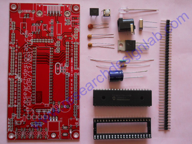
Smart Home Using Matlab GUI Kits Contains:
- PCB and programmed Microcontroller/Processor
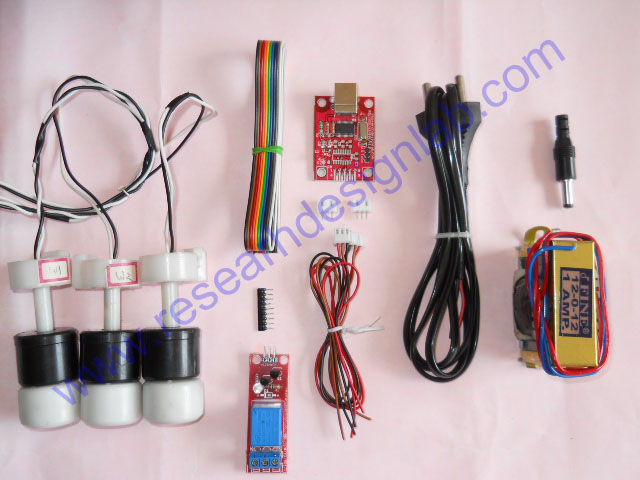
- Water Level Sensors (3)
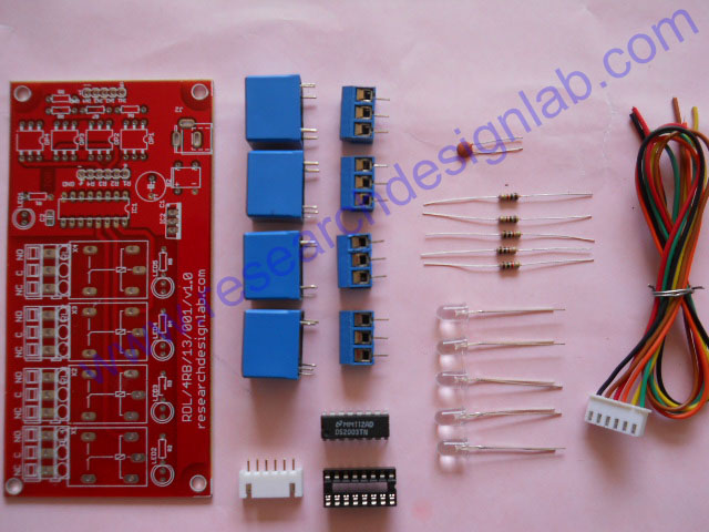
- 4 Relay Board
- 1 Relay Board
- USB to TTL converter
- transformer (12 volts)
- CD/DVD Project Report &CBT(Computer Based Training)*
- Source code and datasheets
Reference :
Above design based on latest IEEE, Spring and other international journal and Publication .The reference paper will be given along with kits.
Smart Home Using Matlab GUI Kits Details:
PIC Controller
|
Sl.no.
|
Components
|
Legend
|
Quantity
|
|
1.
|
40 Pin PIC with IC base
|
IC2
|
1
|
|
2.
|
20MHz crystal oscillator
|
Q1
|
1
|
|
3.
|
Capacitor 33pF
|
C2,C3
|
2
|
|
4.
|
Reset switch
|
S5
|
1
|
|
5.
|
Resistor 1KΩ
|
R5
|
1
|
|
6.
|
Resistor 470Ω
|
R1
|
1
|
|
7.
|
LED
|
LED1
|
1
|
|
8.
|
Capacitor 0.1µF
|
C8
|
1
|
|
9.
|
DC socket
|
J1
|
1
|
|
10.
|
IC DB107
|
B2
|
1
|
|
11.
|
IC 7805
|
IC1
|
1
|
|
12.
|
Capacitor 1000µF
|
(filter capacitor near bridge)
|
1
|
|
13.
|
Burg stick
|
N/A
|
1
|
|
14.
|
PIC project board
|
N/A
|
1
|
4 Relay
|
Sl.no
|
Components
|
Legend
|
Quantity
|
|
1.
|
12V DC Relays
|
RL1,RL2,RL3,RL4
|
4
|
|
2.
|
IC ULN2003 with IC base
|
IC1
|
1
|
|
3.
|
LED
|
LED1,LED2,LED3,LED4,LED5
|
5
|
|
4.
|
Resistor 1KΩ
|
R1, R2, R3, R4, R5
|
5
|
|
5.
|
Screw Connector
|
X1, X2, X3, X4
|
4
|
|
6.
|
6 Pin connector with cable
|
R1,R2,R3,R4,+,GND
|
1
|
|
7.
|
Capacitor 0.1µF
|
C2
|
1
|
|
8.
|
4 relay PCB
|
N/A
|
1
|
Miscellaneous
|
Sl.no
|
Components
|
Legend
|
Quantity
|
|
1.
|
12V DC Relays
|
RL1,RL2,RL3,RL4
|
4
|
|
2.
|
IC ULN2003 with IC base
|
IC1
|
1
|
|
3.
|
LED
|
LED1,LED2,LED3,LED4,LED5
|
5
|
|
4.
|
Resistor 1KΩ
|
R1, R2, R3, R4, R5
|
5
|
|
5.
|
Screw Connector
|
X1, X2, X3, X4
|
4
|
|
6.
|
6 Pin connector with cable
|
R1,R2,R3,R4,+,GND
|
1
|
|
7.
|
Capacitor 0.1µF
|
C2
|
1
|
|
8.
|
4 relay PCB
|
N/A
|
1
|
| Order Processing Time |
3 Working Days |
| Buyer Protection: |
- Full Refund if you don't receive your order
- You can get a full refund if your item is significantly different from described*.
|
LabTested Prototype:
PLEASE NOTE:
- The above images are sample prototype images for PIC controller. The controller/processor will change based on the selection made above (in Controllers/Processor option), and controller/processor software will change accordingly.
- High quality PCB FR4 Grade with FPT Certified.
*Conditions Apply