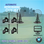
Pay Power Block Diagram:
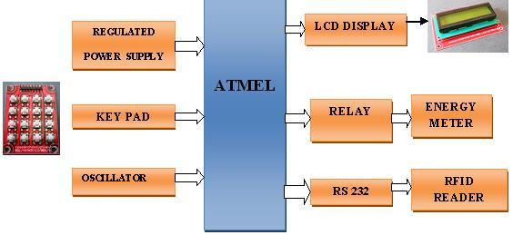
Pay Power Working Principle:
Microcontroller AT89S52 is the heart of the project. It is an 8 bit microcontroller with 8 KB of flash, 256 x 8-bit Internal RAM, 32 Programmable I/O Lines, Three 16-bit Timer/Counters, Eight Interrupt Sources, Full Duplex UART Serial Channel, 4.0V to 5.5V Operating Range and clock circuitry.System clock plays a significant role in operation of the microcontroller. A relay is an electrical switch that opens and closes under the control of another electrical circuit.This project design implements RS-232 protocol for serial communication between microcontroller and PC .A basic radio-frequency identification (RFID) tag is a small and inexpensive microchip that emits a static identifier in response to a query from a nearby reader. Microcontroller will reads the RFID card and based on the number it takes decision , number of units should be provided to the user and It Also monitors the number units consumed by the User. Once the said number of units consumed the electrical power supply gets terminated automatically.
For More Details: Click Here
Controller:
Pay Power Software Requirements:
- LANGUAGE-Embedded C.
- TOOLS: KEIL.
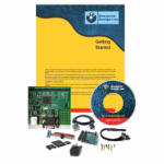
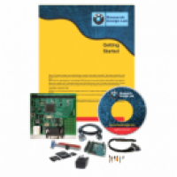
Pay Power Kit Contains:
- PCB programmed Microcontroller
- Energy meter
- RFID Reader
- Relays.
- CD/DVD Project Report &CBT *,
Reference:
Above design based on latest IEEE, spring and other international journal and Publication .The reference paper will be given along with kits.
| Order Processing Time |
3 Working Days |
| Buyer Protection: |
- Full Refund if you don't receive your order
- You can get a full refund if your item is significantly different from described.
|
High quality PCB FR4 Grade with FPT Certified.


