Machine Vision Based Smart Home Block Diagram:
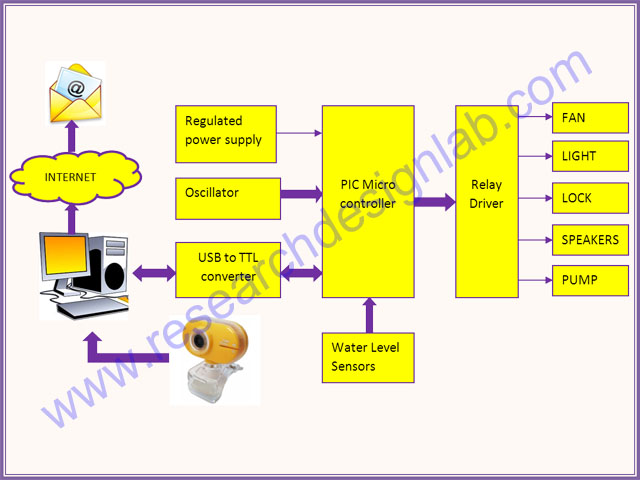
Machine Vision Based Smart Home Working Principle:
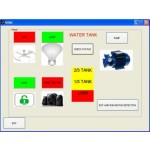
The microcontroller is used to monitor and control the devices. An embedded c program is pre written into the microcontroller which is programmed according to our need. The microcontroller is then interfaced with the relays and the necessary water level sensors. Matlab will send a serial data to the microcontroller via the serial interface. The microcontroller replies if necessary and does the task assigned to it. There are two parts in the matlab Gui, one will behave like a regular user interface for hardware controlling the other will detect motion and fire through camera vision. Matlab will send an email to the concern user if any threat was detected along with a snapshot of the current view.
Controller:
Machine Vision Based Smart Home Software Requirements:
- MATLAB 2008 and above
- LANGUAGE-Embedded C.
- TOOLS: mikroC PRO for PIC/KEIL
Machine Vision Based Smart Home Kits Contains:
- PCB programmed Microcontroller
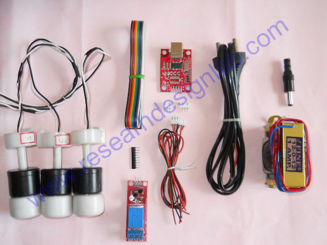
- Water Level Sensors (3)
- 4 Relay Board
- 1 Relay Board
- USB to TTL converter
- transformer (12 volts)
- CD/DVD Project Report &CBT(Computer Based Training)*
- Source code and datasheets
Reference :
Above design based on latest IEEE, Spring and other international journal and Publication .The reference paper will be given along with kits.
Machine Vision Based Smart Home Kits Details:
PIC Controller
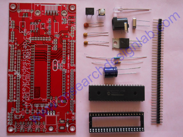
|
Sl.no.
|
Components
|
Legend
|
Quantity
|
|
1.
|
40 Pin PIC with IC base
|
IC2
|
1
|
|
2.
|
20MHz crystal oscillator
|
Q1
|
1
|
|
3.
|
Capacitor 33pF
|
C2,C3
|
2
|
|
4.
|
Reset switch
|
S5
|
1
|
|
5.
|
Resistor 1KΩ
|
R5
|
1
|
|
6.
|
Resistor 470Ω
|
R1
|
1
|
|
7.
|
LED
|
LED1
|
1
|
|
8.
|
Capacitor 0.1µF
|
C8
|
1
|
|
9.
|
DC socket
|
J1
|
1
|
|
10.
|
IC DB107
|
B2
|
1
|
|
11.
|
IC 7805
|
IC1
|
1
|
|
12.
|
Capacitor 1000µF
|
(filter capacitor near bridge)
|
1
|
|
13.
|
Burg stick
|
N/A
|
1
|
|
14.
|
PIC project board
|
N/A
|
1
|
4 Relay
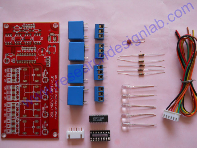
|
Sl.no
|
Components
|
Legend
|
Quantity
|
|
1.
|
12V DC Relays
|
RL1,RL2,RL3,RL4
|
4
|
|
2.
|
IC ULN2003 with IC base
|
IC1
|
1
|
|
3.
|
LED
|
LED1,LED2,LED3,LED4,LED5
|
5
|
|
4.
|
Resistor 1KΩ
|
R1, R2, R3, R4, R5
|
5
|
|
5.
|
Screw Connector
|
X1, X2, X3, X4
|
4
|
|
6.
|
6 Pin connector with cable
|
R1,R2,R3,R4,+,GND
|
1
|
|
7.
|
Capacitor 0.1µF
|
C2
|
1
|
|
8.
|
4 relay PCB
|
N/A
|
1
|
Miscellaneous
|
Sl.no
|
Components
|
Legend
|
Quantity
|
|
1.
|
12V DC Relays
|
RL1,RL2,RL3,RL4
|
4
|
|
2.
|
IC ULN2003 with IC base
|
IC1
|
1
|
|
3.
|
LED
|
LED1,LED2,LED3,LED4,LED5
|
5
|
|
4.
|
Resistor 1KΩ
|
R1, R2, R3, R4, R5
|
5
|
|
5.
|
Screw Connector
|
X1, X2, X3, X4
|
4
|
|
6.
|
6 Pin connector with cable
|
R1,R2,R3,R4,+,GND
|
1
|
|
7.
|
Capacitor 0.1µF
|
C2
|
1
|
|
8.
|
4 relay PCB
|
N/A
|
1
|
| Order Processing Time |
3 Working Days |
| Buyer Protection: |
- Full Refund if you don't receive your order
- You can get a full refund if your item is significantly different from described.
|
LabTested Prototype:
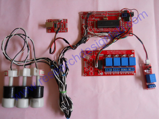
PLEASE NOTE:
- The above images are sample prototype images for PIC controller. The controller/processor will change based on the selection made above (in Controllers/Processor option), and controller/processor software will change accordingly.
- High quality PCB FR4 Grade with FPT Certified.
*Conditions Apply
VIDEO
http://www.youtube.com/watch?v=7KmZKWxvF5U&feature=youtu.be


