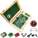
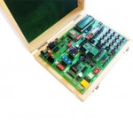
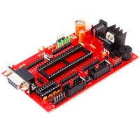
Atmega 328 is one of the most commonly used Micro controllers with open source platform amongst many hobbyist and industrial communities. The simplicity and the low power of Atmega 328 helps design many prototype boards which could be used in numerous applications.The Atmega 328 includes 6 analog inputs, 14 digital I/O pins (6 amongst these could be used as PWM outputs), a crystal oscillator with 16MHz frequency.
Features:
-
Atmega328p- controller and ESP8266 Module.
-
Standard I/O interface.
-
Programmable with Arduino open source IDE.
-
Simple and convenient design for the hobbyist and developers.
-
USB-FT232 Driver.
-
8 independent LED.
-
1 * 4 independent keys.
-
4* 4 keypad matrix.
-
RTC DS1307 with battery connector
-
AT24C02 I2C external memory.
-
I2C EEPROM Interfaces
-
The MAX232 chip RS232 communication.
-
16X2 LCD interface (character display).
-
All IO ports pin have extraction and clearly marked.
-
On Board Power supply 3.3V, 5V 12V, GND.
-
8 pin DIP switches.
-
RS232 Connector.
-
The board also has inbuilt Xbee footprint.
-
3 ADC potentiometers.
-
ON/OFF slide switch.
-
External jumper nodes.
-
Quartz crystal 16 MHz
-
ULN 2803 to drive Stepper Motor& Relays.
-
Reset button.
-
Power plug-in DC Socket.
-
Power supply indicator LED.
-
Test led for TX, Rx.
-
Pin outs for 3.3V, 12V, 5V, GND.
-
All IO’s are connected by burg strips for easy connection.
-
High quality PCB FR4 Grade with FPT Certified.
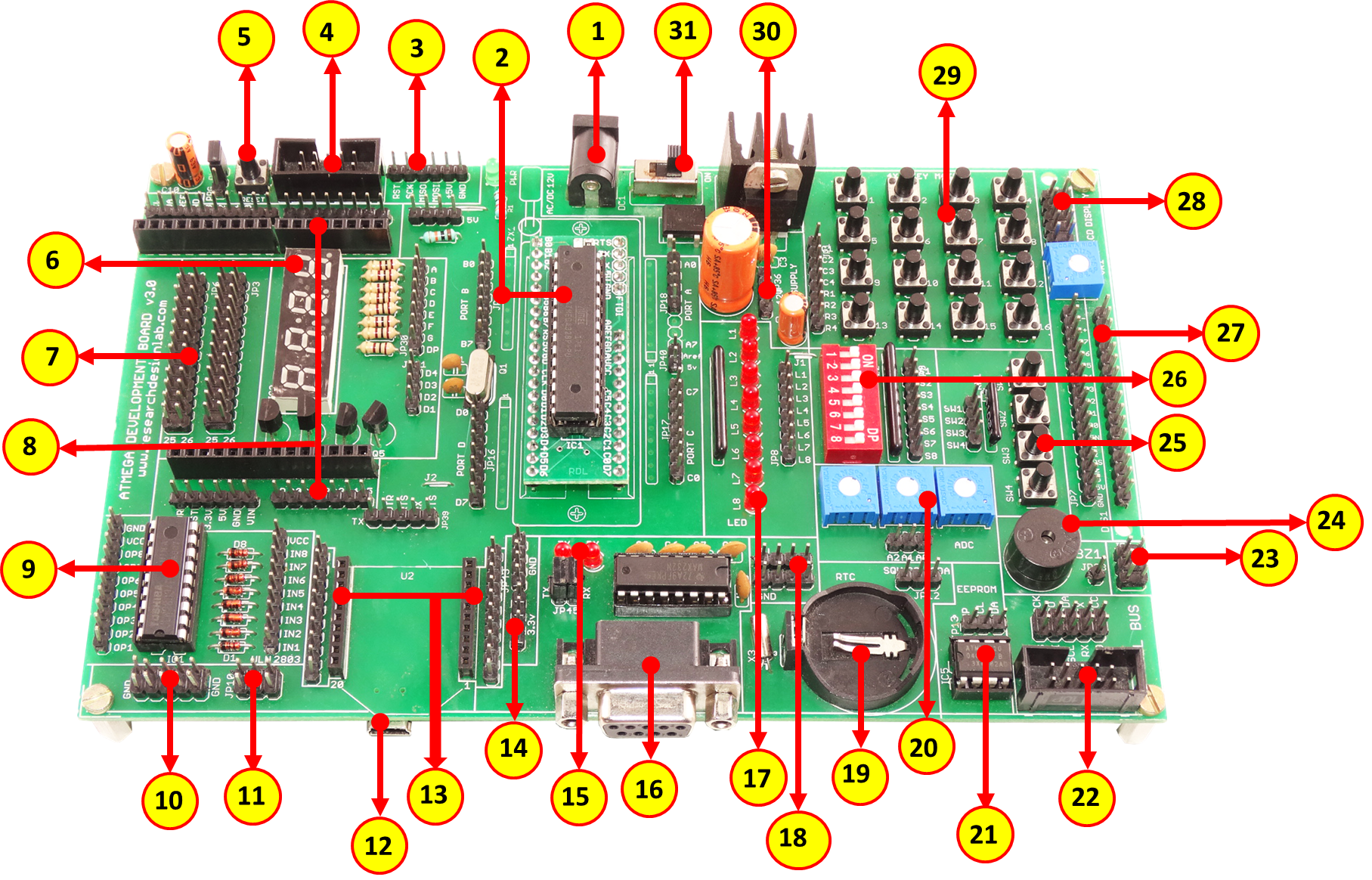
1. Power supply, 5V-12V.
2. Atmega328p- controller.
3. ISP Connector *.
4. ISP FRC Connector*.
5. Reset Switch.
6. 4x1 7 segment display.
7. 26 pin Raspberry Pi connector.
8. Arduino Shield footprint.
9. ULN 2803 driver.
10. GND Connector.
11. Node connector.
12. USB Connector for Communication.
13. XBEE footprint/ XBEE Adaptor module.
14. DC 3.3V connectors.
15. TX RX LED's.
16. DB-9 female connector.
17. 8x1 LED’s.
18. DC 5V connectors.
19. RTC Module.
20. 3 Pot for Analog Variation.
21. EEPROM 24C04 IC.
22. RDL BUS.
23. Node connector.
24. Buzzer.
25. 4x1 keypad.
26. 8 way DIP switch.
27. 16x2 LCD Connector.
28. DC 5V connector.
29. 4x4 Matrix Keypad.
30. DC 12V connectors.
31. Power ON switch.
*It require additional programmer to burn the chip through ICD ICSP socket.
Scope of Learning Experiments:
-
Creating IOT Hub
-
MQTT & Postman
-
Monitoring Nodes
-
Device to Cloud Connection (D2C)
-
Device to Device Connection (D2D)
-
Cloud to Device Connection (C2D)
-
Creating GUI for Nodes
-
Cloud Analytics
-
Machine Learning
-
LED blinking.
-
8 bit LED Left shift, Right shift and counting operation.
-
1X4 Keypad interfacing.
-
16X2 LCD interfacing.
-
4X4 Keypad interfacing.
-
ADC interfacing.
-
8 bit DIP switch interfacing.
-
Buzzer interfacing.
-
7 Segment interfacing.
-
ULN2803 DC Motor and Stepper motor interfacing.
-
ULN2803 Relay interfacing.
-
UART RS232 serial communication.
-
RTC DS1307 I2C protocol interfacing.
-
AT24C04 EEPROM I2C protocol interfacing.
-
Bluetooth interfacing.
-
LoRa interfacing*.
-
RF/WiFi XBEE interfacing*
-
SPI protocol interfacing with RDL product.
-
Arduino GSM/GPRS shield interfacing*
*Existing module.
Package Contains:
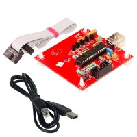
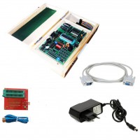
- ATmega328 Development Board.
- ESP8266 Breakout Board.
- BT24 Bluetooth Breakout Board.
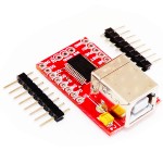
- XBee USB Adapter with FT232RL.
- LCD 2X16.
- Mini USB cable.
- 12V 2A Adafter
- Jumper wires-25No's
- CD
- Serial Cable.
- Wooden Enclousure.


