COM Port
This should be the initial step before using the data logger configuration manager.

Connect the USB Port to the configuration system as shown above

Check the COM Port ![]() Device
Manager
Device
Manager ![]() Ports as
shown
above
Ports as
shown
above
Note: Ensure that you have the FTDI Com port driver loaded. Please download and install from the link provided below if it is not installed.
Link:
https://www.ftdichip.com/Drivers/VCP.htm
For Installation Guide ,
CLICK HERE
Device can be logged in two ways for configuration: 1. Local Login and
2.Remote Login(Refer Page 58 )
Local Login:

1.Click on Com Port Select USB.
2.Select your Com Port and click on Open.

3.Use the Default Password “RDL123” during Login
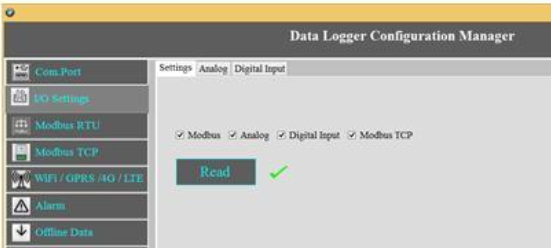
I/O Settings

Select the required I/O options and click on Save button.

This Setting will indicate which digital input needs to be
logged.
1.Select check box ![]() to save the data to the SD Card and click on buttonSave
to save the data to the SD Card and click on buttonSave
2.Select the type of Digital Input (Digital Input High/Low, 32 Bit Counter, Time Enabled Counter)
and click on Save button.
3.Select the Check box![]() to Enable/Disable Digital Input channel and click on Save button.
to Enable/Disable Digital Input channel and click on Save button.
4.Click on Read to display the configuration that is already saved.
Note: Data Logged only when Input channel status changed (From High to Low or Low to High)
Digital Input Specification
- Channels: 4
- Input Voltage: 0-24V
- Logic High: > 5V
- Logic Low: < 4V
- Isolation : 3750 VRMS
- Supports Inverted DI Status
- Supported Connection: Dry and Wet both
- Maximum Switching Frequency : 5Khz
Application Wiring Diagram


Counter Settings

These Settings will configure Digital counter input.
1.Select the Checkbox![]() to Enable/Disable Digital Counter Input channel.
to Enable/Disable Digital Counter Input channel.
2.Set the Max Count
3.Click Save to write these count settings in the memory.
4.Click on Read to display the configuration that is already saved. will display the current max count /
channel.
Note:
1.Data Logged only when Input Channel status changed (From High to Low or Low to High).
2.Data will be pushed to the Remote Server once counter reaches to max set count (Applicable only when
counter option enabled).
3.Once counter reaches the max count then it resets to zero (Applicable only when counter option enabled).
Application Wiring Diagram

Time Enabled Counter
Counting with respect to time in sec

These Settings will configure Digital counter input.
1.Select the Checkbox![]() to Enable/Disable Digital Counter Input channel.
to Enable/Disable Digital Counter Input channel.
2.Set the Time(sec)
3.Click Save to write these count settings in the memory.
4.Click on Read to display the configuration that is already saved. will display the current max count /
channel.
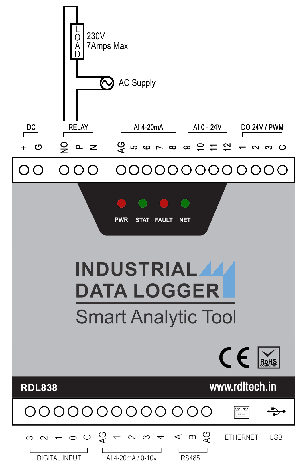
Digital Output
Digital Output Specification
- Channels: 3
- Open Collector
- solation : 3750 VRMS
- Absolute maximum voltage 35V, Current 100mA
- Maximum PWM frequency : 5Khz
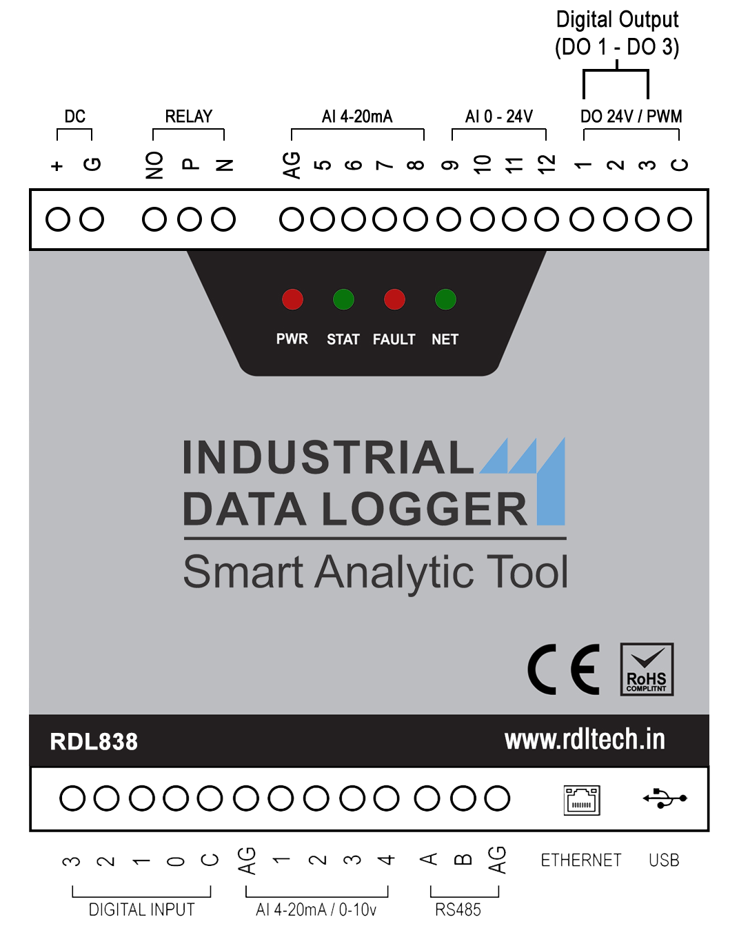
NOTE:Max load current 100mA, 35v In the case of load drawing more current you need to add the additional driver.
Application Wiring Diagram
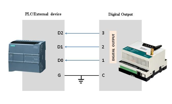
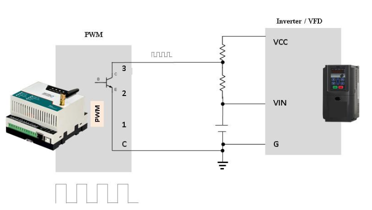
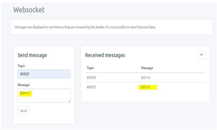
Digital Output:
Digital Output / PWM can controlled directly from server using MQTT Subscribe service.
Command: Digital _Channel =Logic High/ Low
Example:
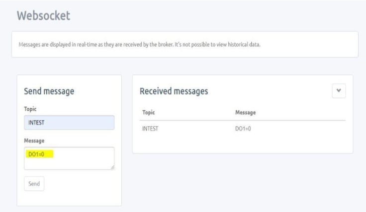
1.DO1=0![]() Digital output (DO) 1 becomes LOW
Digital output (DO) 1 becomes LOW
2.DO1=1![]() Digital output (DO) 1 becomes HIGH
Digital output (DO) 1 becomes HIGH
3.DO2=0![]() Digital output (DO) 2 becomes LOW
Digital output (DO) 2 becomes LOW
4.DO2=1![]() Digital output (DO) 2 becomes HIGH
Digital output (DO) 2 becomes HIGH
5.DO3=0 ![]() Digital output (DO) 3 becomes LOW
Digital output (DO) 3 becomes LOW
6.DO3=1![]() Digital output (DO) 3 becomes HIGH
Digital output (DO) 3 becomes HIGH
NOTE:Digital Output works only for 4G and 2G, it doesn’t support for WiFi Communication.
Digital Output handling using MQTT subscribe service
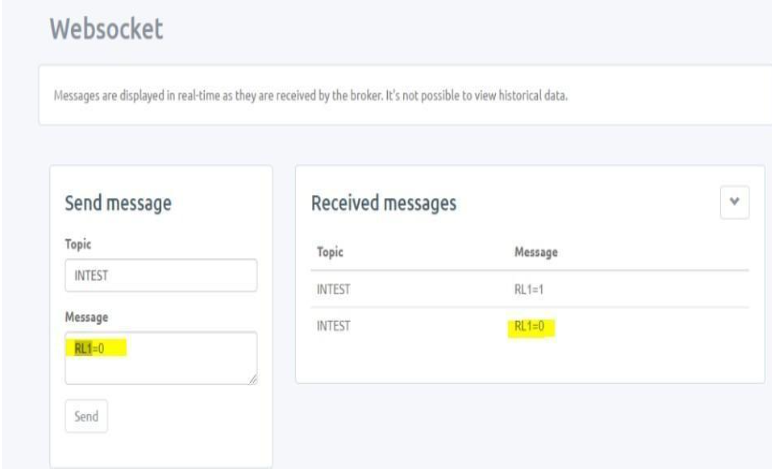
Relay Output
Relay can be controlled directly from server using MQTT Subscribe service.
Command: Relay = Logic High/ Low
Relay output command:
RL1=1 ![]() Relay becomes HIGH
Relay becomes HIGH
RL1=0 ![]() Relay becomes LOW
Relay becomes LOW
Relay Output handling using MQTT subscribe service
Analog
Analog Channel Settings
The below given settings shows how to configure Loop current (4-20mA) and 0-10V Analog Channels.
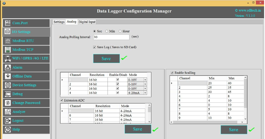
- Select the Polling Interval sec/min/hour
- Set the Polling Interval
- Save Log: Select the Check box
 to store the data to the SD Card.
 - Click on Save button will write these configuration settings in the memory.
- Select the Check box to Enable/Disable Analog channel
- Select 4-20mA / 0-10V from the dropdown.
- Extension ADC is an additional option under this the first four analog channels are for 4-20mA loop current and the next four for 0- 24V channel.
- Scaling: Click on the check boxto enable scaling. Scale the raw value of input to required output value.
- Click on Save button to save the above configuration.
- Click on Read, to display the configuration that is already saved.
Application Wiring Diagram


NOTE:Don’t connect Voltage source when Channel is set for Current Source Mode.
MODBUS RTU
Select the check box![]() for enabling the MODBUS and Click on Save button.
for enabling the MODBUS and Click on Save button.
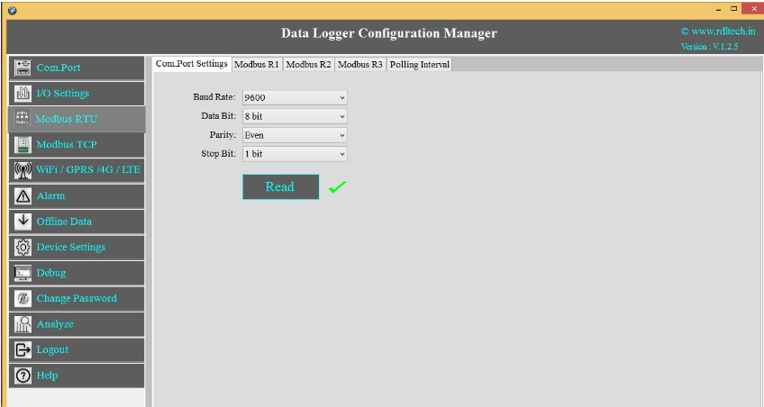
Com Port Settings
1.Click on MODBUS RTU from the side bar menu
2.Click on Read to know the previous stored Configuration.
3.Click on Com Port Settings
a.Select Baud Rate from the dropdown.
b.Select Data Bit from the dropdown.
c.Select Parity from the dropdown.
d.Select Stop Bit from the dropdown.
e.Click on Save button.
f.Click on Read to display the configuration that is already saved., will display the configuration that is already saved.
Based on Meter/Slave type the register polling classified in three Bank R1, R2 and R3.
R1 Register Bank meant for reading maximum 10 slave devices and maximum register length of 100 for each slave.
R2 Register Bank meant for reading maximum 32 similar slave /meters with 30 register length for each slave/meter
R3 Register Bank meant for reading maximum 10 devices with 100 register length for each slave devices and all slaves can be set for different polling time.
NOTE:Maximum 1000+ tags can be polled by combining R1, R2, and R3 Register Banks
MODBUS R1
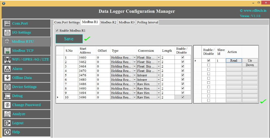
1.Click on the check box![]() to enable MODBUS Register Bank R1, and click on Save button.
to enable MODBUS Register Bank R1, and click on Save button.
2.Enter MODBUS Register details as shown above
3.Enter MODBUS credential.
4.R1 Register Bank supports 10 slave devices for each slave you can configure max length up to 100 register.
5.Select Enable/Disable check box![]() to poll the register.
to poll the register.
6.Click on Save button.
MODBUS R2
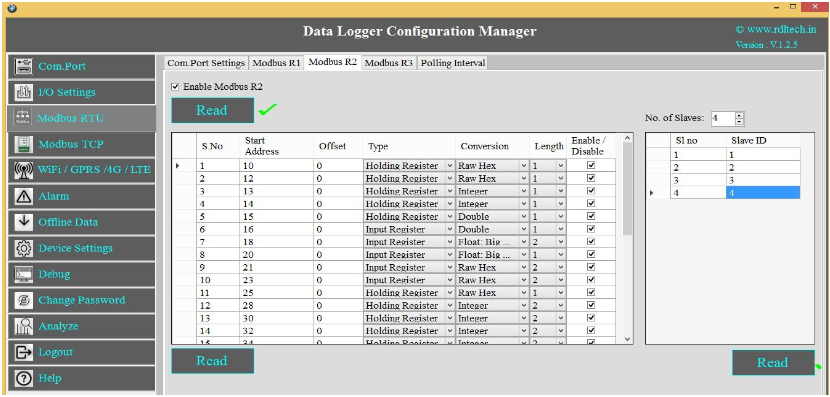
1.Click on the check box![]() to enable MODBUS Register Bank R2, and click on Save button.
to enable MODBUS Register Bank R2, and click on Save button.
2.Enter MODBUS credential as shown above.
This supports for 32 similar slaves/meters with 30 registers length for each slave/meter
3.Select Enable/Disable check box![]() to poll the register
to poll the register
4.Click on Save button.
NOTE:In R2, Address configuration is same for multiple slaves; it has only facility to change Slave ID of each device.
MODBUS R3
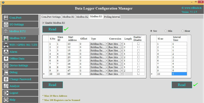
1.Click on the check box![]() to enable MODBUS Register Bank R3, and click on Save button.
to enable MODBUS Register Bank R3, and click on Save button.
2.Enter MODBUS credential as shown above.
This supports 10 slaves, for each slave 10 start registers are available and for each start register configure up to 100 lengths.
3.R3 has the facility to add polling time for each slave ID.
4.Select Enable/Disable check box![]() to poll the register.
to poll the register.
5.Click on Save button.
MODBUS RTU Polling Interval
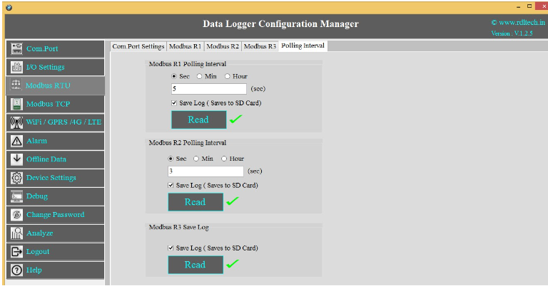
- Select the Polling Interval sec/min/hour.
- Set the MODBUS Polling Interval.
- Click on check box to Save the Log.
- Click on Save button to save the above configuration.
- Click on Read to display the configuration that is already saved.
Application Wiring Diagram

MODBUS TCP Settings

1. Set the Device MAC Address, Data Logger IP, Subnet Mask,
Gateway and click on Save.
2. Slave ID: This is the MODBUS Slave ID. Maximum10 Slave info can be accessed.
3. Slave IP: Mention the IP Address of the Slave.
4.Socket: If the Slave IP address is same for multiple requests then the socket number will be the
same.
If the IP address is different, then the socket number is different as shown above (Ex: For Slave
ID 1 and
3 the slave IP is same (192.168.1.187) so the socket number should be the same (0)).
5.Slave Port No: Mention the Port No. (Default 502).
6.Start Address:6.This is the starting address of the slave from where data needs to be read.
7.Offset: Enter Offset of the Slave device.
8.Type: 8.Mention the register type. It could be Coil/Input Register/Holding Register.
9.Conversion:
Raw Hex: MODBUS 16 bits are extracted from slaves.
Integer: MODBUS 16 bits are extracted from slaves.
Double: MODBUS 16 bits are extracted from slaves.
Float-Big Endian: MODBUS floats are extracted from slaves
in Big Endian format.
Float-Little Endian: MODBUS 16 bits are extracted from
slaves.
64 bit UINT: MODBUS 16 bits are extracted from slaves.
10.Length: Total length will be 100,you can use length of 1-100 of 16 bit data
11.Status: T11.If check box is enabled, the slave id will be ENABLED for polling, else slave id
polling will be DISABLED.
12.Click on Savebutton to save the above configuration.
13.Click on Read to display the configuration that is already saved., to display the configuration that is
already saved
14.Select the Polling Interval sec/min/hour
Note:
1. Device and Slave should be in same network
2. Max 100 registers can be scanned.
Application Wiring Diagram

4G/LTE FTP Settings
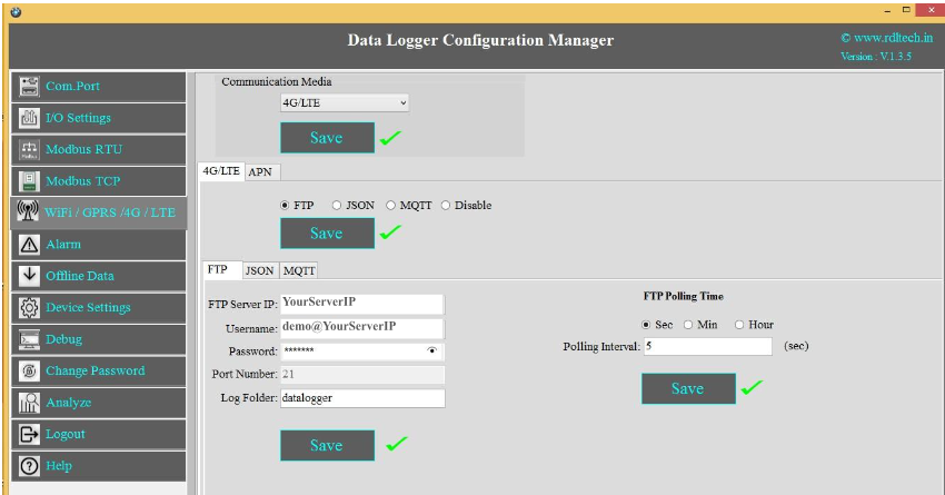
1. Choose 4G/LTE in the Communication Media. Click on Save.
2. Select the protocol FTP and Save.
3. Provide FTP Server IP(Ex:YourServerIP/),Username(Ex:demo@YourServerIP),Password(Ex:abcdef).
4. Log Folder: Provide folder name for the FTP Server(Ex:datalogger).
5. Click on Save will save these settings in the memory.
6. APN: Provide APN for the connection.Click on Save. Ex: for BSNL it is "bsnlnet".
7. FTP Uploading Time: Select the Polling Interval sec/min/hour
8. Click on Save button to save the above configuration.
9. Click on Read to display the configuration that is already saved.
NOTE: FTP Account creating guideline document. Please go through the below given link document.
LINK1:https://github.com/researchdesignlab/Industrial-Data-Logger/blob/master/CREATING%20FTP%20ACCOUNT.pdf
YouTube Link:https://www.youtube.com/watch?v=_MfcA8Jcmtk
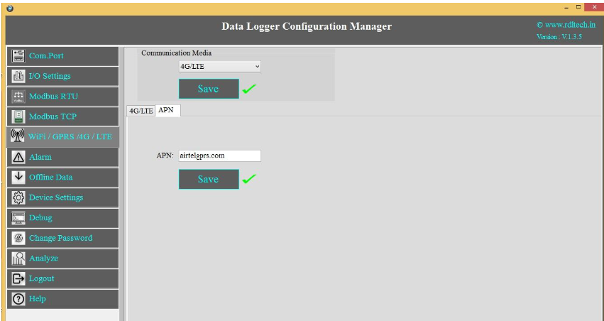
APN: Provide APN for the connection. Click on Save.
Ex: for BSNL 🡪 "bsnlnet".
Airtel 🡪 “airtelgprs.com”
Idea 🡪 “internet”
Data Uploading Format
APN: Provide APN for the connection. Click on Save.
Ex: for BSNL 🡪 "bsnlnet".
Airtel 🡪 “airtelgprs.com”
Idea 🡪 “internet”
4G/LTE FTP Data Uploading Format:
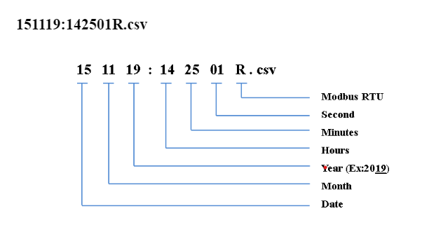
MODBUS RTU Data Uploading Format
File uploading format for given date 15/11/2019 will be
151119:142501R.csv
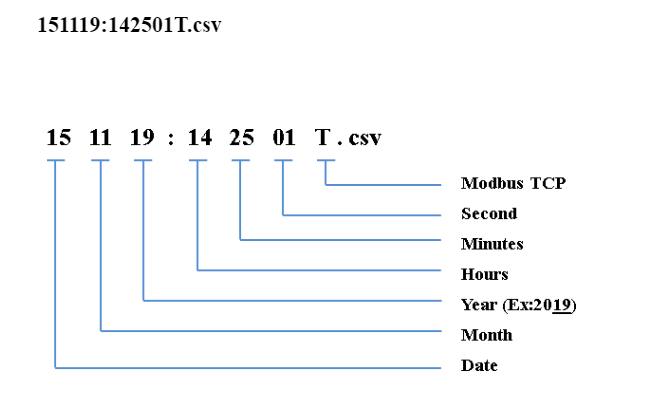
MODBUS TCP Data Uploading Format
File uploading format for given date 15/11/2019 will be
151119:142501T.csv
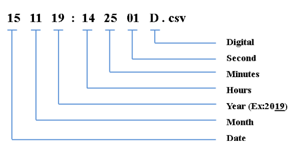
Digital Input Data Uploading Format
File uploading format for given date 15/11/2019 will be
151119:142501D.csv
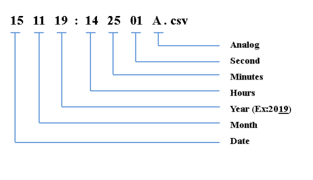
Analog Input Data Uploading Format
File uploading format for given date 15/11/2019 will be
151119:142501A.csv
4G/LTE JSON Settings
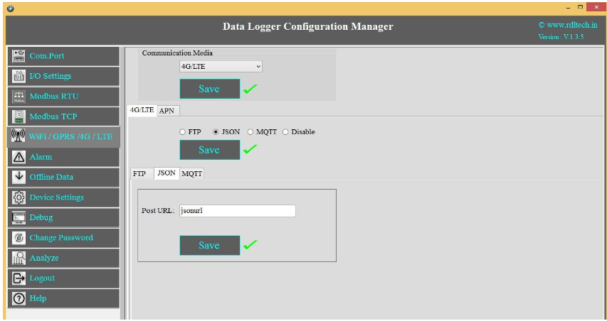
1. Choose 4G/LTE in the Communication Media. Click on Save.
2. Select the protocol JSON and Save.
3. Post URL: Provide Your Server URL(Ex:http://yourdomainname/yourfolder/json.php).
4. Click on Save button to save the above configuration.
5. APN: Provide APN for the connection. Click on Save
Ex: for BSNL it is "bsnlnet".
NOTE: JSON implementation guideline document. Please go through the below given link document.
LINK1:https://github.com/researchdesignlab/Industrial-Data-Logger/blob/master/CREATING%20FTP%20ACCOUNT.pdf
YouTube Link:https://www.youtube.com/watch?v=_MfcA8Jcmtk
4G/LTE JSON Data Uploading Format
MODBUS RTU Data Uploading Format:
JSON FORMAT:
{“Type”:”MR”,”ID”:”1235”,”DATE”:”1/11/19”,”TIME”:”12:47:9”,”SL_ID” :”1”,”Reg
Ad”:”1003”,”Length”:”6”,”D1”:”0”,”D2”:”0”,”D3”:”0”,”D4”:”0”,”D5”:”0”,”D6”:”0”}
NOTE: MODBUS RTU/TCP 16bit/32bit data parsed in hex decimal format.
MODBUS TCP Data Uploading Format:
JSON FORMAT:
{“Type”:”MT”,”ID”:”1123”,”DATE”:”4/11/19”,”TIME”:”12:21:21”,”SL_ID” :”1”,”Reg
Ad”:”1060”,”Length”:”6”,”D1”:”1165”,”D2”:”1166”,”D3”:”1167”,”D4”:”1168”,”D5”:” 1169”,”D6”:”1170”}
NOTE: MODBUS RTU/TCP 16bit/32bit data parsed in hexa decimal format
ANALOG Input Data Uploading Format:
JSON FORMAT:
{"Type":"AN","ID":"6549","DATE":"18/08/21","TIME":"15:54:43","AC1":"0.00","AC2":"0.
00","AC3":"0.00","AC4":"0.00","AC5":"0.00","AC6":"0.00","AC7":"0.00","AC8":"0.00","A C9":"0.00","AC10":"0.00","AC11":"0.00","AC12":"0.00"}
Digital Input Data Uploading Format:
JSON FORMAT:
{“Type”:”DI”,”ID”:”1234”,”DATE”:”2/11/19”,”TIME”:”12:35:15”,”DC1”:”0”,”D C2”:” 0”,”DC3”:”0”,”DC4”:”0”}
4G/LTE MQTT Settings
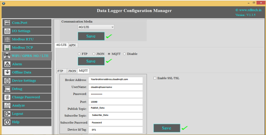
1. Choose 4G/LTE in the Communication Media. Click on Save.
2. Select the protocol MQTT and Save.
3. Broker Address: Enter your broker address of MQTT(Ex:yourbrokeraddress.cloudmqtt.com).
4. Cloud Username: Enter MQTT cloud Username(Ex:Cloudmqttusername).
5. Password: Enter MQTT cloud Password(Ex:abcdef).
6. Port: Enter Port number for MQTT cloud(Ex:15590).
7. Publish Topic: Enter Topic name to publish the data to server(Ex:Publish_Data).
8. Subscribe Topic: To receive the data from the server(Ex:Subscribe_Data)
9. Device Id/Tag: Enter the Device ID(Ex:DT1)
10. Click on Save will save these settings in the memory.
11. APN:Enter APN for the connection. Ex: for BSNL it is "bsnlnet".
12. Click on Save.
NOTE: MQTT Broker creating guideline document. Please go through the below given link document.
LINK1:https://github.com/researchdesignlab/Industrial-Data-Logger/blob/master/MQTT_Linux_Bringup_ver1.0.pdf
LINK2 https://www.cloudmqtt.com/docs/com_port.html
YouTube Link: https://www.youtube.com/watch?v=qNFmfBpNMsg&t=3s
4G/LTE MQTT Data Parsing Format:
MODBUS RTU Data Parsing Format:
Parsing Format:
{“Type”:”MR”,”ID”:”1235”,”DATE”:”1/11/19”,”TIME”:”12:47:9”,”SL_ID” :”1”,”Reg
Ad”:”1003”,”Length”:”6”,”D1”:”0”,”D2”:”0”,”D3”:”0”,”D4”:”0”,”D5”:”0”,”D6”:”0”}
NOTE: MODBUS RTU/TCP 16bit/32bit data parsed in hexadecimal format
MODBUS TCP Data Parsing Format:
Parsing Format:
{“Type”:”MT”,”ID”:”1123”,”DATE”:”4/11/19”,”TIME”:”12:21:21”,”SL_ID” :”1”,”Reg
Ad”:”1060”,”Length”:”6”,”D1”:”1165”,”D2”:”1166”,”D3”:”1167”,”D4”:”1168”,”D5”:”1 169”,”D6”:”1170”}
NOTE:MODBUS RTU/TCP 16bit/32bit data parsed in hexadecimal format.
ANALOG Input Data Parsing Format:
Parsing Format:
{"Type":"AN","ID":"6549","DATE":"18/08/21","TIME":"15:54:43","AC1":"0.00","AC2":"0.00","AC3
":"0.00","AC4":"0.00","AC5":"0.00","AC6":"0.00","AC7":"0.00","AC8":"0.00","AC9":"0.00","AC10": "0.00","AC11":"0.00","AC12":"0.00"}
NOTE:For Analog Input configuration look into the section 2.2 in this document
Digital Input Data Parsing Format:
Parsing Format:
{“Type”:”DI”,”ID”:”1234”,”DATE”:”2/11/19”,”TIME”:”12:35:15”,”DC1”:”0”,”DC2”:” 0”,”DC3”:”0”,”DC4”:”0”}
4G/LTE MQTT with SSL Settings
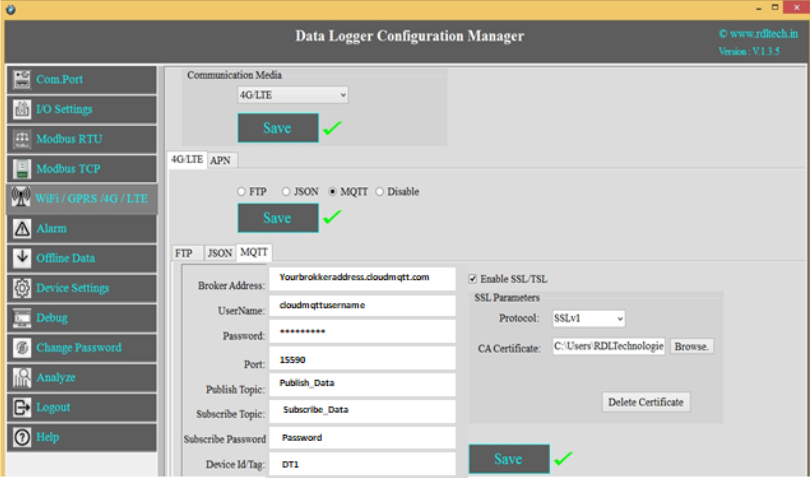
1. Choose 4G/LTE in the Communication Media. Click on Save.
2. Select the protocol MQTT and Save.
3. Broker Address: Enter your broker address of MQTT(Ex:yourbrokeraddress.cloudmqtt.com).
4. Cloud Username: Enter MQTT cloud Username(Ex:Cloudmqttusername).
5. Password: Enter MQTT cloud Password(Ex:abcdef).
6. Port: Enter Port number for MQTT cloud(Ex:15590).
7. Publish Topic: Enter Topic name to publish the data to server(Ex:Publish_Data).
8. Subscribe Topic: To receive the data from the server(Ex:Subscribe_Data)
9. Device Id/Tag: Enter the Device ID(Ex:DT1)
10. Click on Enable SSL/TSL and set the SSL Parameters.
11. Protocol: Select in the dropdown which protocol you are using.
12. CA Certificate: Please upload the CA Certificate.
13. Click on Save button to save the above configuration.
14. Click on Delete Certificate to delete the uploaded Certificate.
15. APN: Provide APN for the connection. Ex: for BSNL ->"bsnlnet".Click on Apply.
NOTE:Make sure that power supply connected during the process of uploading the SSL certificate
Wi-Fi Settings
Wi-Fi DHCP Settings
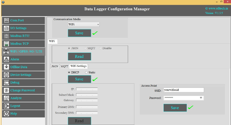
1. Choose Wi-Fi in the Communication Media. Click on Save.
2. Wi-Fi Settings are enabled now.
3. Select protocol MQTT/JSON and click on Save button.
4. Wi-Fi Settings: Select DHCP. Click on Apply.
5. Access Point: Set the SSID (Ex:yourwifissid) and Password (EX:abdcdef).
6. Click on Save button to save these settings in the memory.
Wi-Fi Static Settings
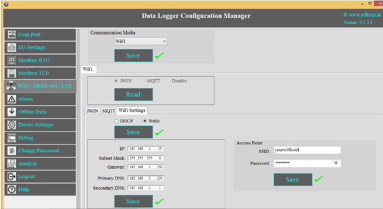
1. Choose Wi-Fi in the Communication Media. Click on Save.
2. Select the protocol JSON
3. Wi-Fi Settings: Select Static. Click on Apply.
4. Enter the IP, Subnet Mask, Gateway, Primary DNS, Secondary DNS and click on Save.
5. Access Point: Set the SSID (Ex:yourwifissid) and Password(Ex:abcdef), Click on Save
button.
Wi-Fi JSON Settings
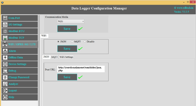
1. Choose Wi-Fi in the Communication Media. Click on Save.
2. Wi-Fi Settings: Select the protocol JSON and Save.
3. Post URL: Provide Your Server URL.(Ex: http://yourdomainname/yourfolder/json.php)
4. Click on Save button to save the above configuration.
Wi-Fi JSON Data Uploading Format
MODBUS RTU Data Uploading Format
API FORMAT:
{“Type”:”MR”,”ID”:”1235”,”DATE”:”1/11/19”,”TIME”:”12:47:9”,”SL_ID” :”1”,”Reg
Ad”:”1003”,”Length”:”6”,”D1”:”0”,”D2”:”0”,”D3”:”0”,”D4”:”0”,”D5”:”0”,”D6”:”0”}
NOTE:MODBUS RTU/TCP 16bit/32bit data parsed in hexadecimal format
MODBUS TCP Data Uploading Format
API FORMAT:
{“Type”:”MT”,”ID”:”1234”,”DATE”:”4/11/19”,”TIME”:”12:21:21”,”SL_ID” :”1”,”Reg
Ad”:”1060”,”Length”:”6”,”D1”:”1165”,”D2”:”1166”,”D3”:”1167”,”D4”:”1168”,”D5”:”1
169”,”D6”:”1170”}
NOTE:MODBUS RTU/TCP 16bit/32bit data parsed in hexadecimal format
Analog Input Data Uploading Format
API FORMAT:
{"Type":"AN","ID":"6549","DATE":"18/08/21","TIME":"15:54:43","AC1":"0.00","AC2":"0.00","AC3
":"0.00","AC4":"0.00","AC5":"0.00","AC6":"0.00","AC7":"0.00","AC8":"0.00","AC9":"0.00","AC10":
"0.00","AC11":"0.00","AC12":"0.00"}
Digital Input Data Uploading Format
API FORMAT:
{“Type”:”DI”,”ID”:”1234”,”DATE”:”2/11/19”,”TIME”:”12:35:15”,”DC1”:”0”,”DC2”:”
0”,”DC3”:”0”,”DC4”:”0”}
Wi-Fi MQTT Settings
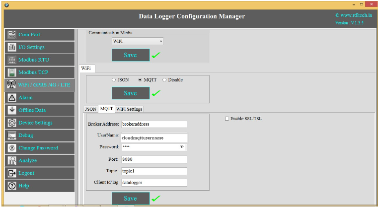
1. Choose Wi-Fi in the Communication Media. Click on Save.
2. Wi-Fi Settings are enabled now, ready for MQTT
3. MQTT: Data logging happens to MQTT server. Click on Save.
4. Broker Address: Provide your broker address of MQTT (Ex: yourbrokeraddress.cloudmqtt.com)
5. Cloud Username: Provide MQTT cloud Username.(Ex: Cloudmqttusername)
6. Password: Provide MQTT cloud Password.(Ex:abcdef).
7. Port: Provide Port number for MQTT cloud.(Ex:15590)
8. Topic:Provide Topic name.(Ex:Topic1)
9. Device Id/Tag: Provide the Device ID(Ex:datalogger)
10. Click on Save button to save the above configuration.
Wi-Fi MQTT Data Parsing Format:
MODBUS RTU Data Parsing Format:
Parsing Format:
{“Type”:”MR”,”ID”:”1235”,”DATE”:”1/11/19”,”TIME”:”12:47:9”,”SL_ID” :”1”,”Reg
Ad”:”1003”,”Length”:”6”,”D1”:”0”,”D2”:”0”,”D3”:”0”,”D4”:”0”,”D5”:”0”,”D6”:”0”}
NOTE:MODBUS RTU/TCP 16bit/32bit data parsed in hexadecimal format
MODBUS TCP Data Parsing Format
Parsing Format:
{“Type”:”MT”,”ID”:”1123”,”DATE”:”4/11/19”,”TIME”:”12:21:21”,”SL_ID” :”1”,”Reg
Ad”:”1060”,”Length”:”6”,”D1”:”1165”,”D2”:”1166”,”D3”:”1167”,”D4”:”1168”,”D5”:”1 169”,”D6”:”1170”}
NOTE:MODBUS RTU/TCP 16bit/32bit data parsed in hexadecimal format
Analog Input Data Parsing Format:
Parsing Format:
{"Type":"AN","ID":"6549","DATE":"18/08/21","TIME":"15:54:43","AC1":"0.00","AC2
":"0.00","AC3":"0.00","AC4":"0.00","AC5":"0.00","AC6":"0.00","AC7":"0.00","AC8":" 0.00","AC9":"0.00","AC10":"0.00","AC11":"0.00","AC12":"0.00"}
Digital Input Data Parsing Format:
Parsing Format:
{“Type”:“DI”,”ID”:”1234”,”DATE”:”2/11/19”,”TIME”:”12:35:15”,”DC1”:”0”,”DC2”:” 0”,”DC3”:”0”,”DC4”:”0”}
Alarm
Device sends emergency alerts and different Escalation level SMS to the remote user on real time basis. Device also supports Automating the remote asset based on set threshold. Alarm can be applied for Digital, Analog and Modbus Inputs.
Setting up Alarm for Digital Input:
1. Enable Digital I/O and Click on Save button.
2. Click on Channel 1 and select Alert Settings tab and Enable it and then Save.
3. Alert Message Escalation Level, enable the Levels, set the Threshold Time, enter the contact number and write the alert message to be sent and click on Save button.
4.Maximum 5 phone numbers and maximum 25 character length alert messages can be registered.
NOTE:If digital Input is triggered then send a configured message to the configured number based on threshold time priority.
Automated Digital I/O Alarm Task:
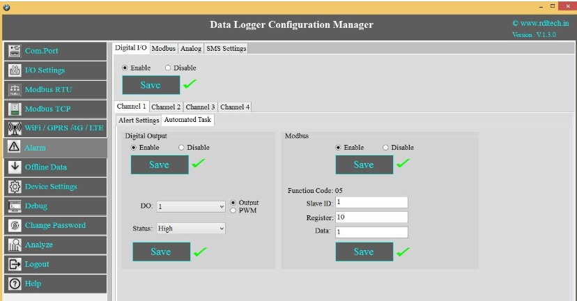
Case 1: Automate Task when Digital Input Channel 1 goes High, make the Digital Output Channel High.
To do the above task, follow the below given steps:
1.Click on Channel 1.
2.Click on Automated Task tab and enable the Digital Output and Save.
3.Select the Digital Output Channel
4.Make the bit status High/Low.
5.Click on Save button to save the above configuration.
Case 2: Automate Task when Digital Input Channel 1 goes High ,write data to slave ID 1 and register ID 10.
To do the above task, follow the below given steps:
1.Click on Channel 1.
2.Click on Automated Task tab and enable the Digital Output and Save.
3.Select the Digital Output Channel
4. Make the bit status High/Low.
5.Enable the MODBUS and Click on Save button.
6.Enter the Slave ID, Register address and Data.
7.Click on Save button to save the above configuration
Setting up Alarm for MODBUS:
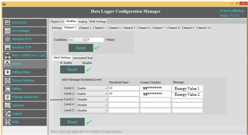
1. Select MODBUS, Click on Channel 1 and select Alert Settings tab and Enable it and then Save.
2. Alert Message Escalation Level, enable the Levels, set the Threshold Time, enter the contact number and write the alert message to be sent and click on Save button.
3. Maximum 5 phone numbers and maximum 25 character length alert messages can be registered.
NOTE:MODBUS Alarm is linked to MODBUS Register Bank R3.
MODBUS Register Bank R3 set slave received value match with an alarm registered condition and value, if the condition is successful, then send a configured message to the configured number based on threshold time and escalation priority.
Automated MODBUS Alarm Task:
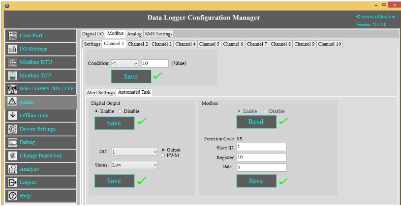
Case 1: Automate Task when MODBUS Channel 1 goes High, make Digital Output Channel High.
To do the above task, follow the below given steps:
1.Click on Channel 1 and select Automated Task tab and Enable it and then Save.
2.Select the Digital Output Channel
3.Make the bit status High/Low.
4.Click on Save button to save the above configuration.
Case 2: Automate Task when MODBUS Input Channel 1 goes High , write data to slave ID 1 and register ID 10.
To do the above task, follow the below given steps:
1.Click on Channel 1 and select Automated Task and Enable it and then Save
2.Select the Digital Output Channel
3.Make the bit status High/Low.
4.Enable the MODBUS and Click on Save button.
5.Enter the Slave ID, Register address and Data.
6.Click on Save button to save the above configuration
Setting up Alarm for Analog:
1. Click on Analog and select the Channels (A1-A12) and Click on Enable and Save.
2. Select Alert Settings tab and Enable it and then Save
3. Alert Message Escalation Level, enable the Levels, set the Threshold Time, enter the contact number and write the alert message to be sent and click on Save button.
4.Maximum 5 phone numbers and maximum 25 character length alert messages can be registered.
NOTE:Analog value, match with an alarm registered condition and value, if the condition is successful, then send a configured message to the configured number based on threshold time priority.
Automated MODBUS Alarm Task:
Case 1: Automate Task when Analog Channel 1 goes High, make Digital Output Channel High.
To do the above task, follow the below given steps:
1.Click on Channel 1 and select Automated Task tab and Enable it and then Save
2.Select the Digital Output Channel
3.Make the bit status High/Low.
4.Click on Save button to save the above configuration.
Case 2: Automate Task when Analog Input Channel 1 goes High, write data to slave ID 1 and Register ID 10.
To do the above task, follow the below given steps:
1.Click on Channel 1 and select Automated Task tab and Enable it and then Save
2.Select the Digital Output Channel
3.Make the bit status High/Low.
4.Enable the MODBUS and Click on Save button.
5.Enter the Slave ID, Register address and Data and Save it.
Offline Data
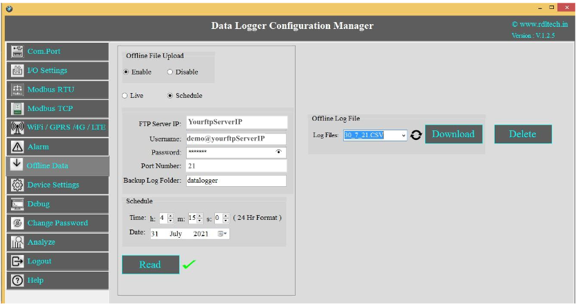
1.Enable: Select enable to upload the file offline/when there is no internet connectivity.
2. Select radio button to Enable/Disable offline file
3.Live: Offline data sent to a configured server after receiving an internet connection.
4.Schedule: Offline data is stored in the “jsn_bup.txt” file. That file is sent to the Configured FTP Server at configured time.
5.FTP Details: Enter the FTP Server IP (Ex:yourftpServerIP), Username
(Ex:demo@yourftpserverIP), Password(Ex:abcdefg) and the Port Number
6.Click on Save button.
7.Backup Log Folder: Enter FTP server folder name(In case of multiple folder enter folder name with path)
8.Schedule: Set the Time and Date for offline data FTP poll.
9.Offline Log Data:
Log Files: You can select the .CSV files
Download: You can select the Log files from the Dropdown and Click on Download.
Delete: You can select the Log files which you want to delete from the Dropdown and click on Delete.
Device Settings
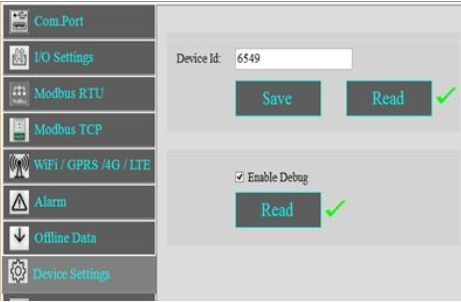
1.Set the Device Id (Ex:6549) and click on Save
2.Click on Read to display the configuration that is already saved.
3.Select the Enable Debug and click on Save.
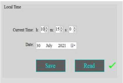
1.Set the device Current time in hour, minute and seconds.
2.Date: Select the date from the drop down menu.
3.Click on Save to save the above configuration.
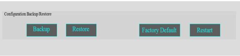
1.Click on Backup to take the entire data logger configuration backup.
2.Click on Restore and select the file to restore the data logger Configuration.
3.Factory Default: Click on Factory Default to restore the factory default configuration settings.
4.Restart: Click on Restart button to restart the Data Logger.
Change Password
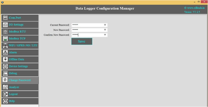
You can change the default password by entering the New Password.
Remote Login
NOTE:(Before Configuring the Remote, make sure that under Local login you have selected GPRS/WIFI. (For Ex:If you want to select GPRS in Remote ,first you need to configure GPRS in Local Login. Similarly if Wifi in Remote then you need to configure WiFi in Local Login).
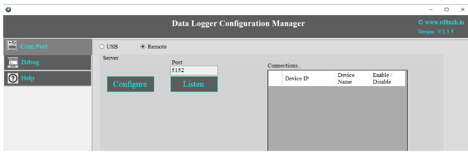
1.Click on Com port and Select Remote from the radio button.
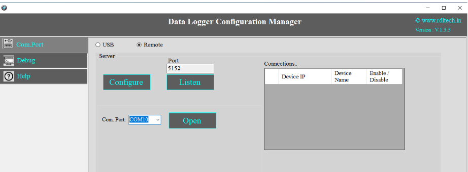
2.Click on Configure
3.Select the Com Port and click on Open
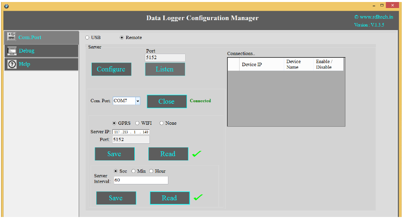
1.Click on Configure and Choose WiFi or GPRS from the radio button and enter the IP address.
2.In GPRS Configuration use Public IP address. If the configuration is Wi-Fi then you can use Private or Public IP addresses.
3.Click on Save Button
4.Click on Read to display the configuration that is already saved. will display the configuration that is already saved
5.Enter the Server Interval time(Ex: 60sec) of connection.
6.Click on Save.
7.Close the Com Port which is Open
8.Click on Listen
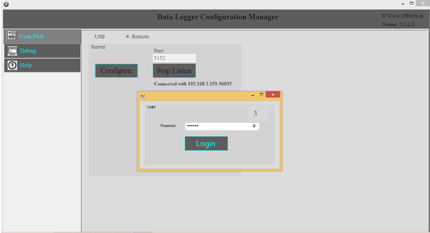
1.Use the Default Password “RDL123” during Login
2.For next step Page 5
Power Supply Connection
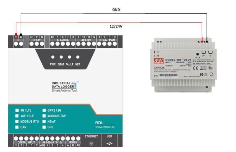
ATTENTION:Recommended to use Meanwell power supplies of 24V 2A
Setting Up On-premises Web Server
Step 1: Install XAMPP Application
- Download and install XAMPP.
- After installation, enable both Apache and MySQL services.
Step 2: Create Database and Tables
- In XAMPP, click on the MySQL Admin button to open the phpMyAdmin page.
- Create a new database named device and import the necessary tables.
Step 3: Establish Database Connection and Create Insert & Retrieve Links
- After creating the database, place your project folder inside the following path: C:/Xampp/htdocs/ I already have the folder name as Device. This folder should contain three files: dbConnection.php, jsonUpload.php, and jsonRetrive.php.
- In the connection file, ensure that the database name matches the one you created.
- To check if the database connection is successful, access the following link using your system's IP address: http://192.168.1.147/Device/dbConnection.php. If it displays a blank page, the connection is successfully established.
- Next, upload your data by accessing the following link: http://192.168.1.147/Device/jsonUpload.php.
- Finally, check the retrieval functionality using this link: http://192.168.1.147/Device/jsonRetrive.php.
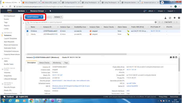
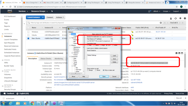
Steps to configure and bring up Mosquitto MQTT Broker on AWS EC2/Linux
Mainly 2 steps
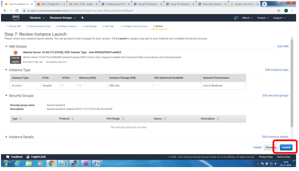
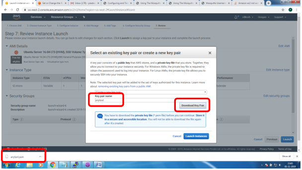
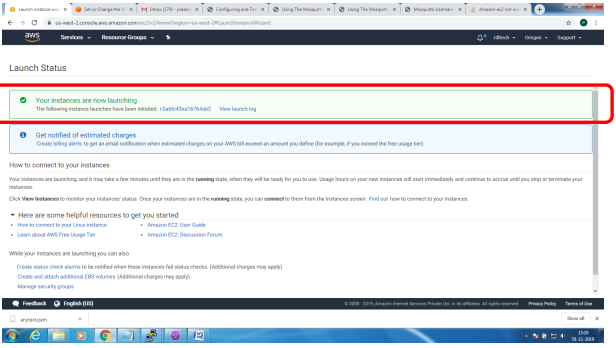
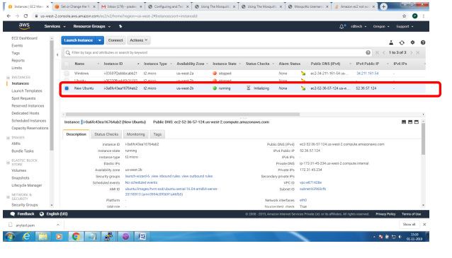
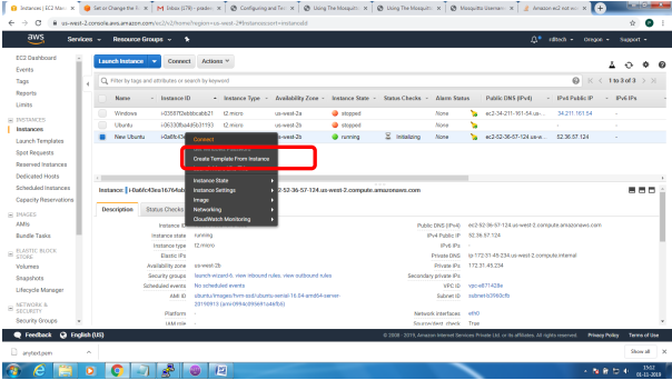
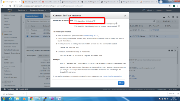
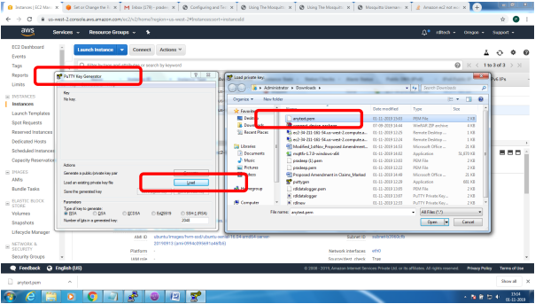
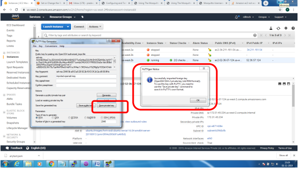
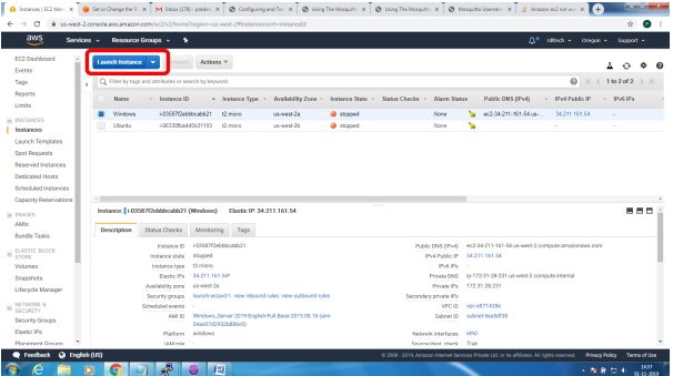
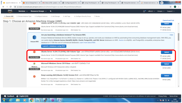
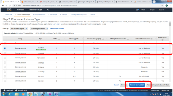
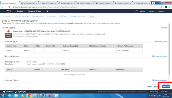
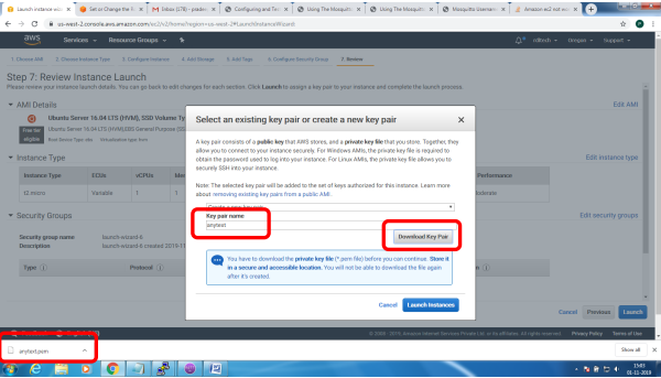
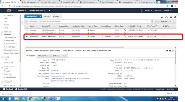
1. Bring up EC2 Linux System
2. Install mosquitto on the above system
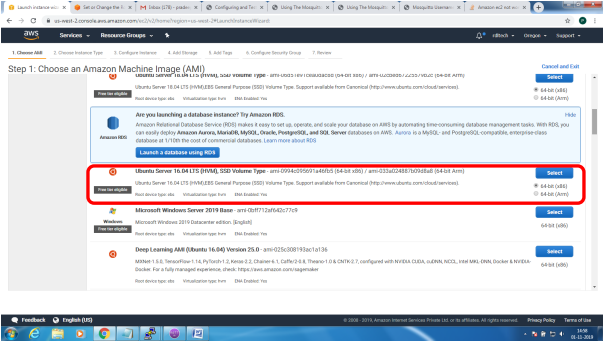
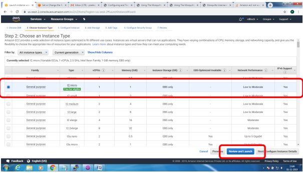
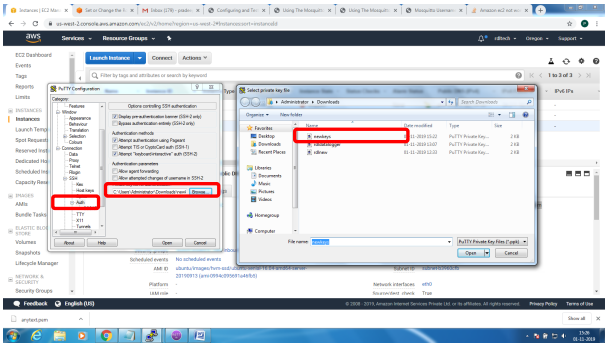
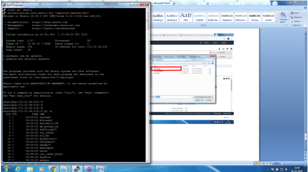
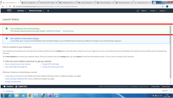
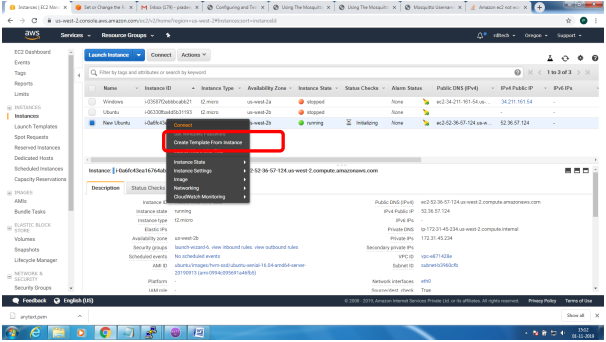
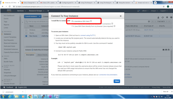
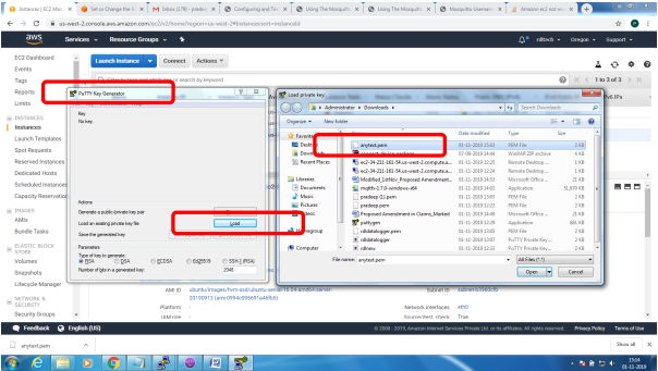
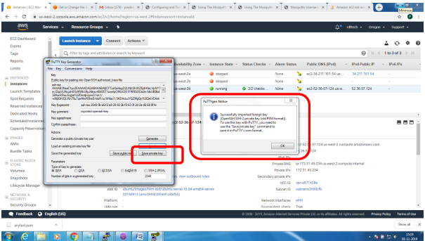
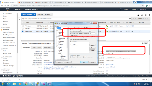
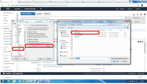
Bring up EC2 Linux System
Installation of mosquitto on linux system
Follow the below steps to install mosquitto
- sudo apt-add-repository ppa:mosquitto-dev/mosquitto-ppa
- sudo apt-get update
- sudo apt-get install mosquitto
- sudo apt-get install mosquitto-clients
Follow the below steps to Enable user authentication
- Create a txt file in the following format
- Username:Password
- Issue the following commands to add certificate to this file
- mosquitto_passwd -U passwordfile (text file name)
- Copy this file to /etc/mosquitto
Open mosquiito.conf and add these 2 lines to enable user authentication
allow_anonymous false
password_file etc\mosquitto\passwords.txt
Restart the broker to absorb the changes
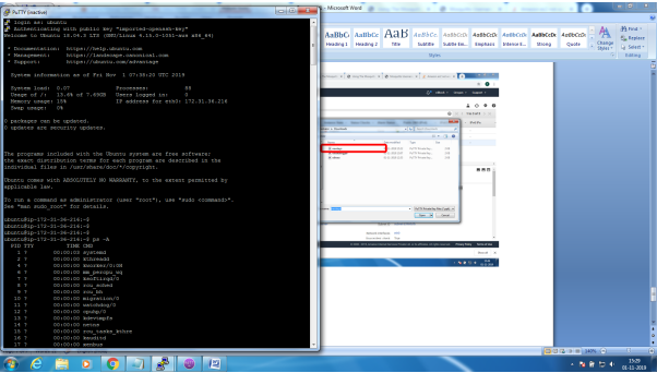
ubuntu@ip-172-31-36-216:~$ mosquitto -v
1572603369: mosquitto version 1.6.7 starting
1572603369: Using default config.
1572603369: Opening ipv4 listen socket on port 1883.
Error: Address already in use
To resolve this
ps –ef | grep mosquitto
kill -9 pid
mosquitto_sub -t '$SYS/#' –v
or
root@ip-172-31-36-216:/home/ubuntu# mosquitto
1572603616: mosquitto version 1.6.7 starting
1572603616: Using default config.
1572603616: Opening ipv4 listen socket on port 1883.
1572603616: Opening ipv6 listen socket on port 1883.
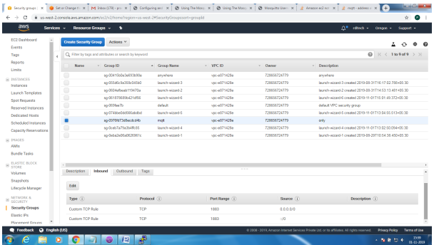
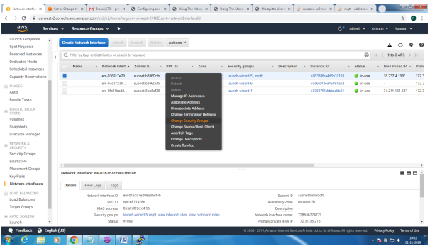
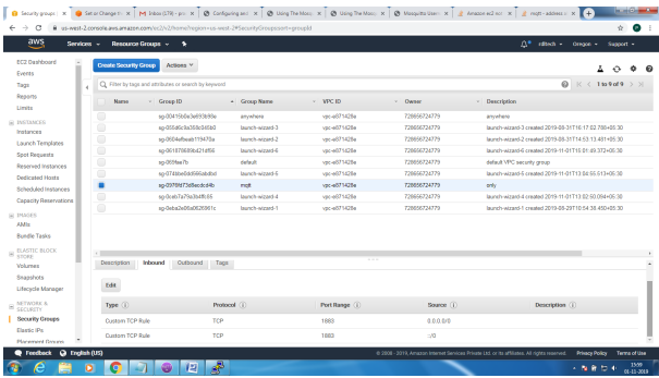
To enable Message flow on to AWS ES2 system, follow the below steps
Create Security Group to allow TCP/1883 traffic in the inbound direction
Setting up MQTT Broker on SSL Implementation
Mainly 2 steps
1. Bring up EC2 Linux System
2. Install mosquitto on the above system
Bring up EC2 Linux System
Installation of mosquitto on linux system
Follow the below steps to install mosquitto
- sudo apt-add-repository ppa:mosquitto-dev/mosquitto-ppa
- sudo apt-get update
- sudo apt-get install mosquitto
- sudo apt-get install mosquitto-clients
Follow the below steps to Enable user authentication
- Create a txt file in the following format
- Username:Password
- Issue the following commands to add certificate to this file
- mosquitto_passwd -U passwordfile (text file name)
- Copy this file to /etc/mosquitto
Open mosquiito.conf and add these 2 lines to enable user authentication
allow_anonymous false
password_file etc\mosquitto\passwords.txt
Restart the broker to absorb the changes
ubuntu@ip-172-31-36-216:~$ mosquitto -v
1572603369: mosquitto version 1.6.7 starting
1572603369: Using default config.
1572603369: Opening ipv4 listen socket on port 1883.
Error: Address already in use
To resolve this
ps –ef | grep mosquitto
kill -9 pid
mosquitto_sub -t '$SYS/#' –v
or
root@ip-172-31-36-216:/home/ubuntu# mosquitto
1572603616: mosquitto version 1.6.7 starting
1572603616: Using default config.
1572603616: Opening ipv4 listen socket on port 1883.
1572603616: Opening ipv6 listen socket on port 1883.
To enable Message flow on to AWS ES2 system, follow the below steps
Create Security Group to allow TCP/1883 traffic in the inbound direction
Mosquitto SSL Configuration -MQTT TLS Security
Server Side:
Openssl tool is used to generate the required keys and certificats for both the server and client
Issue the following commands in sequence and make changes to the mosquitto.conf on the server
for the changes to take effect
1. openssl genrsa -des3 -out ca.key 2048
2. openssl req -new -x509 -days 1826 -key ca.key -out ca.crt
3. openssl genrsa -out server.key 2048
4. openssl req -new -out server.csr -key server.key
5. openssl x509 -req -in server.csr -CA ca.crt -CAkey ca.key -CAcreateserial -out
server.crt -days 360
The directory file listing would look similar to the below
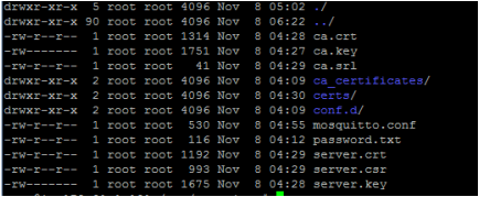
Copy the ca.crt, server.crt and server.key file to /etc/mosquitto/cert folder
Make the following changes to the mosquitto.conf file
Add the following lines
Port 8883
Cafile /etc/mosquitto/certs/ca.crt
Keyfile /etc/mosquitto/certs/server.key
Certfile /etc/mosquitto/certs/server.crt
Most important step is to copy the ca.crt on to the client system.
Incase its get challenging to transfer this file, as it would from AWS EC2 environment. Please use
notepad+ (not plain notepad) to copy paste the certificate contents
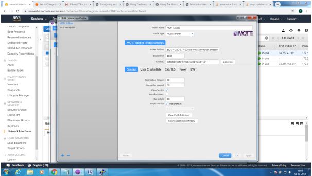
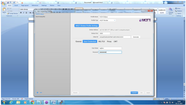
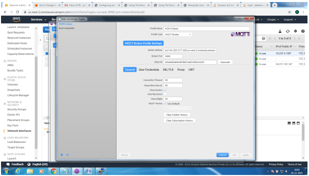
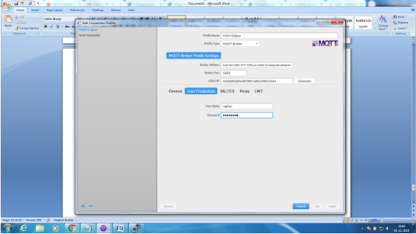
Client Side: Configure the MQTT Client with the broker address, enable SSL and point to the ca.crt
file and connect for application