
Product Description
Related Products


Tags (0)
Reviews (0)
Frequently bought together
Customers who bought this product also commonly purchased the following combination of items.

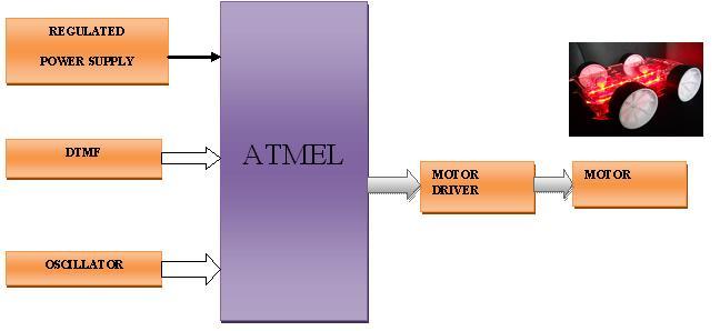
- This Item: Cell Phone Operated Landrover-ATMEL
-
Pay Power-PIC
-
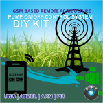
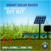
DIY GSM Based Remote Agriculture Pump ON/OFF Control System kit- ARM
-
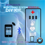
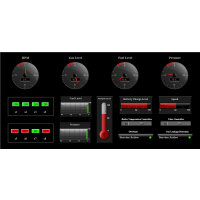
DIY Smart Health Monitoring System Kit-PIC
-
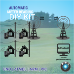
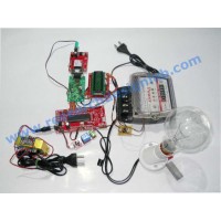
DIY Automatic Meter Reading Kit-PIC
-
Customers Who Bought This Item Also Bought

There are no product questions yet.