COM Port
This should be the initial step before using the data logger configuration manager.

Connect the USB Port to the configuration system as shown above

Check the COM Port ![]() Device
Manager
Device
Manager ![]() Ports as
shown
above
Ports as
shown
above
Note: Ensure that you have the FTDI Com port driver loaded. Please download and install from the link provided below if it is not installed.
Link:
https://www.ftdichip.com/Drivers/VCP.htm
For Installation Guide ,
CLICK HERE
Device can be logged in two ways for configuration: 1. Local Login and
2.Remote Login(Refer Page 58 )
Local Login:

1.Click on Com Port Select USB.
2.Select your Com Port and click on Open.

3.Use the Default Password “RDL123” during Login
I/O Settings

Select the required I/O options and click on Save button.

This Setting will indicate which digital input needs to be
logged.
1.Select check box to save the data to the SD Card and click on buttonSave
2.Select the type of Digital Input (Digital Input High/Low, 32 Bit Counter, Time Enabled Counter)
and click on Save button.
3.Select the Check box to Enable/Disable Digital Input channel and click on Save button.
4.Click on Read to display the configuration that is already saved.
Note: Data Logged only when Input channel status changed (From High to Low or Low to High)
Digital Input Specification
- Channels: 4
- Input Voltage: 0-24V
- Logic High: > 5V
- Logic Low: < 4V
- Isolation : 3750 VRMS
- Supports Inverted DI Status
- Supported Connection: Dry and Wet both
- Maximum Switching Frequency : 5Khz

Application Wiring Diagram


Counter Settings

These Settings will configure Digital counter input.
1.Select the Checkbox to Enable/Disable Digital Counter Input channel.
2.Set the Max Count
3.Click Save to write these count settings in the memory.
4.Click on Read to display the configuration that is already saved. will display the current max count /
channel.
Note:
1.Data Logged only when Input Channel status changed (From High to Low or Low to High).
2.Data will be pushed to the Remote Server once counter reaches to max set count (Applicable only when
counter option enabled).
3.Once counter reaches the max count then it resets to zero (Applicable only when counter option enabled).
Application Wiring Diagram

Time Enabled Counter
Counting with respect to time in sec

These Settings will configure Digital counter input.
1.Select the Checkbox to Enable/Disable Digital Counter Input channel.
2.Set the Time(sec)
3.Click Save to write these count settings in the memory.
4.Click on Read to display the configuration that is already saved. will display the current max count /
channel.
MODBUS TCP Settings

1. Set the Device MAC Address, Data Logger IP, Subnet Mask,
Gateway and click on Save.
2. Slave ID: This is the MODBUS Slave ID. Maximum10 Slave info can be accessed.
3. Slave IP: Mention the IP Address of the Slave.
4.Socket: If the Slave IP address is same for multiple requests then the socket number will be the
same.
If the IP address is different, then the socket number is different as shown above (Ex: For Slave
ID 1 and
3 the slave IP is same (192.168.1.187) so the socket number should be the same (0)).
5.Slave Port No: Mention the Port No. (Default 502).
6.Start Address:6.This is the starting address of the slave from where data needs to be read.
7.Offset: Enter Offset of the Slave device.
8.Type: 8.Mention the register type. It could be Coil/Input Register/Holding Register.
9.Conversion:
Raw Hex: MODBUS 16 bits are extracted from slaves.
Integer: MODBUS 16 bits are extracted from slaves.
Double: MODBUS 16 bits are extracted from slaves.
Float-Big Endian: MODBUS floats are extracted from slaves
in Big Endian format.
Float-Little Endian: MODBUS 16 bits are extracted from
slaves.
64 bit UINT: MODBUS 16 bits are extracted from slaves.
10.Length: Total length will be 100,you can use length of 1-100 of 16 bit data
11.Status: T11.If check box is enabled, the slave id will be ENABLED for polling, else slave id
polling will be DISABLED.
12.Click on Savebutton to save the above configuration.
13.Click on Read to display the configuration that is already saved., to display the configuration that is
already saved
14.Select the Polling Interval sec/min/hour
Note:
1. Device and Slave should be in same network
2. Max 100 registers can be scanned.
Application Wiring Diagram

install Flash Magic Utility
1. Visit FlashMagic website http://www.flashmagictool.com/ and download the
file FlashMagic.exe
2. Execute the downloaded file FlashMagic.exe, and follow the instructions.
3. Start Flash Magic by selecting it from the Start Menu. In the Flash Magic windows select Options
> Advanced Options ... menu item. In the window that appears enable the check box that
says Use DTR and RTS to control RST and P0.14, and click on O
When this option is enabled, during code download, the flashing tool will automatically switch
the device into ISP mode. For more information on this, see the board user manual.

Code
#include"Cloud_PLC.h"

// Default PWM properties
int freq = 5000;     // PWM frequency in Hz
int ledChannel = 0;  // PWM channel (0-15)
int resolution = 8;  // PWM resolution (8 bits, 0-255)


void Cloud_PLC_PWM(int frequency, int pwmResolution)
 {
  freq = frequency;
  resolution = pwmResolution;

  ledcSetup(ledChannel, freq, resolution);
  ledcAttachPin(NETWORK_LED, ledChannel);//PIN NO 12
}

// Function to increase brightness
void increaseBrightness()
{
  for (int dutyCycle = 0; dutyCycle <= 255; dutyCycle++)
{
    ledcWrite(ledChannel, dutyCycle);
    delay(15);
  }
}

// Function to decrease brightness
void decreaseBrightness()
{
  for (int dutyCycle = 255; dutyCycle >= 0; dutyCycle--)
 {
    ledcWrite(ledChannel, dutyCycle);
    delay(15);
  }
}

void setup()
 {
  Cloud_PLC_PWM(freq, resolution); // Call Cloud_PLC_PWM with default values
}

void loop()
{
  increaseBrightness();
  decreaseBrightness();
}
Note
![]() Libraries, User Manuals and Installation guides look into the
download section.
Libraries, User Manuals and Installation guides look into the
download section.
![]() Install
the Cloud PLC libraries(cloudplc.h) before getting start with coding. Download
Install
the Cloud PLC libraries(cloudplc.h) before getting start with coding. Download
![]() Above
download link, you will find all the IO functionalities included in the Cloud PLC library.
Above
download link, you will find all the IO functionalities included in the Cloud PLC library.
![]() In the
Arduino IDE, go to the Boards Manager, select the ESP32 board, and ensure that you have selected the board
version is 1.0.4.
In the
Arduino IDE, go to the Boards Manager, select the ESP32 board, and ensure that you have selected the board
version is 1.0.4.
Library Files (LibFiles)
Basically “LibFiles” contains“system_lpc21xx.c” “.h” files. Before executing lab programs it is important to have this library files in our system as we are going to link our programs to this folder. Place “LibFiles” folder in a common path in all the computers. (ex: C->Documents->ARM->LibFiles)
Code
#include "Cloud_PLC.h"   // This line includes the necessary library for using Cloud PLC functions.

  void setup()
 {
  Cloud_PLC_initialisation();
}
  void loop()
{
  Cloud_PLC_Relay_state(0, HIGH);  //Relay1 channel, State is ON
  delay(1000);
  Cloud_PLC_Relay_state(0, LOW);  // Relay1 is OFF
  delay(1000);
  Cloud_PLC_Relay_state(1, HIGH);  // Relay2 is ON
  delay(1000);
  Cloud_PLC_Relay_state(1, LOW);  // Relay2 is OFF
  delay(1000);
}
Note
![]() Libraries, User Manuals and Installation guides look into the
download section.
Libraries, User Manuals and Installation guides look into the
download section.
![]() Install
the Cloud PLC libraries(cloudplc.h) before getting start with coding. Download
Install
the Cloud PLC libraries(cloudplc.h) before getting start with coding. Download
![]() Above
download link, you will find all the IO functionalities included in the Cloud PLC library.
Above
download link, you will find all the IO functionalities included in the Cloud PLC library.
![]() In the
Arduino IDE, go to the Boards Manager, select the ESP32 board, and ensure that you have selected the board
version is 1.0.4.
In the
Arduino IDE, go to the Boards Manager, select the ESP32 board, and ensure that you have selected the board
version is 1.0.4.
New Project in Keil µVision4
1. Open the Keil software and select “Project-> New µvision
project” as shown below.

2. Browse to your project folder (/Create a folder) and provide the project name and click on save
3. Once the project is saved a new pop up “Select Device for Target” opens, Select the controller (NXP:LPC2148) and click on OK
4. Select the controller (NXP:LPC2148) and click on OK

5. As LPC2148 needs the startup code, click onYes option to include the LPC21xx Startup file

6. Create a new file to write the program.

7. Type the code or Copy paste the below code snippet.

8. After typing the code save the file as main.c

9. Add the recently saved file to the project.

10. Add the“main.c” along with system_LPC21xx.c

11.Build the project and fix the compiler errors/warnings if any

12. Code is compiled with no errors. The .hex file is still not generated. Follow section 4 (how to enable HexFile Generation)

Code
#include "Cloud_PLC.h"

void setup()
{
    Serial.begin(115200);
    Cloud_PLC_config_readADC();  // Configure the ADC
}

void loop()
{
    // Read and print voltages for all channels
    float voltage0 = Cloud_PLC_getVoltage(0);
    float voltage1 = Cloud_PLC_getVoltage(1);
    float voltage2 = Cloud_PLC_getVoltage(2);
    float voltage3 = Cloud_PLC_getVoltage(3);

    // Print voltages
    Serial.print("\tAnalog0: "); Serial.print(voltage0, 2); Serial.print(" V\t");
    Serial.print("\tAnalog1: "); Serial.print(voltage1, 2); Serial.print(" V\t");
    Serial.print("\tAnalog2: "); Serial.print(voltage2, 2); Serial.print(" V\t");
    Serial.print("\tAnalog3: "); Serial.print(voltage3, 2); Serial.print(" V\t");
    Serial.println();

    delay(1000);  // Adjust delay as needed
}
Note
![]() Libraries, User Manuals and Installation guides look into the
download section.
Libraries, User Manuals and Installation guides look into the
download section.
![]() Install
the Cloud PLC libraries(cloudplc.h) before getting start with coding. Download
Install
the Cloud PLC libraries(cloudplc.h) before getting start with coding. Download
![]() Above
download link, you will find all the IO functionalities included in the Cloud PLC library.
Above
download link, you will find all the IO functionalities included in the Cloud PLC library.
![]() In the
Arduino IDE, go to the Boards Manager, select the ESP32 board, and ensure that you have selected the board
version is 1.0.4.
In the
Arduino IDE, go to the Boards Manager, select the ESP32 board, and ensure that you have selected the board
version is 1.0.4.
Enable Hex File Generation
1. Click onTarget Options (or right click on “Target 1”and select “Options for Target ‘Target 1’…) to select the option for generating .hex file.

2. Set IROM1 start address as 0x0000.

3. Enable the option to generate the .hex file

4. Hex file is generated after a rebuild.

5. Check the project folder for the generated .hex file.

Code
#include "Cloud_PLC.h"  // This line includes the necessary library for using Cloud PLC functions.

void setup()
{
  Serial.begin(115200);           // Initializes the serial communication at a baud rate of 115200 bps.
  Cloud_PLC_config_read4_20mA();  // Configures the Cloud PLC to read 4-20 mA inputs.
}

void loop()
{
  for (int i = 0; i < 4; i++)
  {
    Serial.print("Channel ");  // Print the word "Channel"
    Serial.print(i + 1);       // Print the channel number (1 to 4)
    Serial.print(": ");
    Serial.print(Cloud_PLC_read4_20mA(i), 2);   // Prints the value from the channel "i" to the serial monitor with two decimal places
    Serial.print(" mA");
    if (i < 3)
    {
      Serial.print(", ");  // Add a comma and space between readings on the same line
    }
  }
  Serial.println();  // Moves the cursor to the next line in the serial monitor
  delay(1000);       // Delay for readability
}
Note
![]() Libraries, User Manuals and Installation guides look into the download section.
Libraries, User Manuals and Installation guides look into the download section.
![]() Install
the Cloud PLC libraries(cloudplc.h) before getting start with coding. Download
Install
the Cloud PLC libraries(cloudplc.h) before getting start with coding. Download
![]() Above
download link, you will find all the IO functionalities included in the Cloud PLC library.
Above
download link, you will find all the IO functionalities included in the Cloud PLC library.
![]() In the
Arduino IDE, go to the Boards Manager, select the ESP32 board, and ensure that you have selected the board
version is 1.0.4.
In the
Arduino IDE, go to the Boards Manager, select the ESP32 board, and ensure that you have selected the board
version is 1.0.4.
Upload Hex file Using Flash Magic
Once the “.hex” file is generated in keil, we need to
upload the hex file to the hardware. We
use Flash Magic Tool for the same
Open the flash magic software and follow the below steps.
1. Select the IC“LPC2148”from Select Menu.
2. Select the COM Port. Check the device manager for detected Com port.
3. Select Baud rate from 9600-115200
4. Select None [ISP] Option for Interface.
5. Oscillator Frequency 12.000000(12Mhz).
6. Check the Erase blocks used by Hex file option
7. Browse and Select the hex file.
8. Check the Verify After Programming Option.
9. If DTR and RTS are used then go to Options->Advanced Options-> Hardware Config and select
the Use DTR and RTS Option.
10.Hit the Start Button to flash the hex file.
11.Once the hex file is flashed, reset the board. Now the controller should run your application
code.

Code
#include <Cloud_PLC.h>

void setup(void)
 {
  // Initialize Serial communication
  Serial.begin(115200);
  while (!Serial)
    delay(10);  // will pause Zero, Leonardo, etc until serial console opens

    Serial.println("Cloud PLC DAC TEST");

  // cloud_PLC_initialize
  Cloud_PLC_initDAC();

  // Set DAC values
  setDACValue(MCP4728_CHANNEL_A, 2048);// channel 1  5V will be scaled from  0-2048
  setDACValue(MCP4728_CHANNEL_B, 4095);// channel 2 10V will be scaled from 0-4095
  // You can add more calls to setDACValue for other channels if needed
}

void loop()
 {
  // Your loop code here
  delay(1000);
}
Note
![]() Libraries, User Manuals and Installation guides look into the
download section.
Libraries, User Manuals and Installation guides look into the
download section.
![]() Install
the Cloud PLC libraries(cloudplc.h) before getting start with coding. Download
Install
the Cloud PLC libraries(cloudplc.h) before getting start with coding. Download
![]() Above
download link, you will find all the IO functionalities included in the Cloud PLC library.
Above
download link, you will find all the IO functionalities included in the Cloud PLC library.
![]() In the
Arduino IDE, go to the Boards Manager, select the ESP32 board, and ensure that you have selected the board
version is 1.0.4.
In the
Arduino IDE, go to the Boards Manager, select the ESP32 board, and ensure that you have selected the board
version is 1.0.4.
Upload Hex file Using Philips Flash Utility
Once the “.hex” file is generated in keil, we need to
upload the hex file to the hardware. We
use Flash Magic Tool for the same.
Open the flash magic software and follow the below steps.
1. Press theRead Device ID option in the Software. Automatically detects the IC.
2.Select the COM Port. . Check the device manager for detected Com port.
3. Select Baud rate from 9600-115200
4. ClickUse DTR/RTS for Reset and Boot Loader Selection.
5. Check the Erase blocks used by Hex file option.
6.Click Execute Code after Upload.
7. Browse and Select the hex file.
8. Click Upload to Flash.
9. Once the hex file is flashed, reset the board. Now the controller should run your application
code.

Code
#include <Cloud_PLC.h>
void setup(void)
{
  // Initialize Serial communication
  Serial.begin(115200);
  while (!Serial)
    delay(10);  // will pause Zero, Leonardo, etc until serial console opens
  Serial.println("Cloud PLC 4-20mA TEST");
  // cloud_PLC_initialize
  Cloud_PLC_4_20output();
  // Set DAC values
  Cloud_PLC_set4_20output(MCP4728_CHANNEL_C, 4095);  // channel 1 20mA
  Cloud_PLC_set4_20output(MCP4728_CHANNEL_D, 0);     //channel 2 4mA
  // You can add more calls to Cloud_PLC_set4_20output for other channels if needed
}
void loop()
{

  delay(1000 ); // Your loop code here
}
Note
![]() Libraries, User Manuals and Installation guides look into the
download section.
Libraries, User Manuals and Installation guides look into the
download section.
![]() Install
the Cloud PLC libraries(cloudplc.h) before getting start with coding. Download
Install
the Cloud PLC libraries(cloudplc.h) before getting start with coding. Download
![]() Above
download link, you will find all the IO functionalities included in the Cloud PLC library.
Above
download link, you will find all the IO functionalities included in the Cloud PLC library.
![]() In the
Arduino IDE, go to the Boards Manager, select the ESP32 board, and ensure that you have selected the board
version is 1.0.4.
In the
Arduino IDE, go to the Boards Manager, select the ESP32 board, and ensure that you have selected the board
version is 1.0.4.
Blinking an LED
Aim: Interfacing LED’s with ARM LPC2148.
Description:
Interfacing LED’s with ARM LPC2148.
Hardware Requirement:
ARM LPC2148 Trainer Kit, FRC cables, USB A to B cable and 12V 2A Adapter

Program:
#include<LPC21xx.h>
void delay1(int); //define delay function
int main()
{
PINSEL0=0x00000000; //select pins for blinking led
IODIR0=0x00ffffff; //select I/O pins as output
while(1)
{
 IOSET0=0x00ffffff; //sets pins high
 delay1(1000); //gives 1 SEC delay
 IOCLR0=0x00ffffff; //clears pins
 delay1(1000); //gives 1 SEC delay
}
}
/* Delay routine; gives an approximate delay in milliseconds */
void delay1(int d) // delay routine
{
int i;
 while(d)
 {
for(i=0;i<7000;i++){;}
 d--;
 }
 }
Note
![]() Libraries, User Manuals and Installation guides look into the
download section.
Libraries, User Manuals and Installation guides look into the
download section.
![]() Install
the Cloud PLC libraries(cloudplc.h) before getting start with coding. Download
Install
the Cloud PLC libraries(cloudplc.h) before getting start with coding. Download
![]() Above
download link, you will find all the IO functionalities included in the Cloud PLC library.
Above
download link, you will find all the IO functionalities included in the Cloud PLC library.
![]() In the
Arduino IDE, go to the Boards Manager, select the ESP32 board, and ensure that you have selected the board
version is 1.0.4.
In the
Arduino IDE, go to the Boards Manager, select the ESP32 board, and ensure that you have selected the board
version is 1.0.4.
Liquid Crystal Display
Aim: Interfacing LCD Display with ARM LPC2148
Description:
To display the message on the LCD screen.
Hardware Requirement:
ARM LPC2148 Trainer Kit,FRC cables,USB A to B cable and 12V 2A Power Adapter.

Program:
#include<LPC21xx.h>
#include <lpc214x.h>
  #include <stdint.h>
  #include <stdlib.h>
  #include <stdio.h>
  void delay_ms(uint16_t j) /* Function for delay in milliseconds */
  {
   uint16_t x,i;
  for(i=0;i<j;i++)
  {
   for(x=0; x<6000; x++); /* loop to generate 1 millisecond delay with Cclk = 60MHz */
  }
  }
  void LCD_CMD(char command)
  {
  IO0PIN = ( (IO0PIN & 0xFF0FFFFF) | ((command & 0xF0)<<16) ); /* Upper nibble of command */
  IO0SET = 0x00020000; /* EN = 1 */
  IO0CLR = 0x00010000; /* RS = 0, RW = 0 */
  delay_ms(5);
  IO0CLR = 0x00020000; /* EN = 0, RS and RW unchanged(i.e. RS = RW = 0) */
  delay_ms(5);
  IO0PIN = ( (IO0PIN & 0xFF0FFFFF) | ((command & 0x0F)<<20) ); /* Lower nibble of command */
  IO0SET = 0x00020000; /* EN = 1 */
  IO0CLR = 0x00010000; /* RS = 0, RW = 0 */
  delay_ms(5);
  IO0CLR = 0x00020000; /* EN = 0, RS and RW unchanged(i.e. RS = RW = 0) */
  delay_ms(5);
  }
  void LCD_INIT(void)
  {
  IO0DIR = 0x00FFFFF0; /* P0.20 to P0.23 LCD Data. P0.16,,17 as RS RW and EN */
  delay_ms(20);
  LCD_CMD(0x02); /* Initialize lcd in 4-bit mode */
  LCD_CMD(0x28); /* 2 lines */
  LCD_CMD(0x0C); /* Display on cursor off */
  LCD_CMD(0x06); /* Auto increment cursor */
  LCD_CMD(0x01); /* Display clear */
  LCD_CMD(0x80); /* First line first position */
  }
  void LCD_STRING (char* msg)
  {
  uint8_t i=0;
  while(msg[i]!=0)
  {
  IO0PIN = ( (IO0PIN & 0xFF0FFFFF) | ((msg[i] & 0xF0)<<16) );
  IO0SET = 0x00030000; /* RS = 1, EN = 1 */
  IO0CLR = 0x00000020; /* RW = 0 */
  delay_ms(2);
  IO0CLR = 0x00020000; /* EN = 0, RS and RW unchanged(i.e. RS = 1, RW = 0) */
  delay_ms(5);
  IO0PIN = ( (IO0PIN & 0xFF0FFFFF) | ((msg[i] & 0x0F)<<20) );
  IO0SET = 0x00030000; /* RS = 1, EN = 1 */
  IO0CLR = 0x00000020; /* RW = 0 */
  delay_ms(2);
  IO0CLR = 0x00020000; /* EN = 0, RS and RW unchanged(i.e. RS = 1, RW = 0) */
  delay_ms(5);
  i++;
  }
  }
  void LCD_CHAR (char msg)
  {
  IO0PIN = ( (IO0PIN & 0xFF0FFFFF) | ((msg & 0xF0)<<16) );
  IO0SET = 0x00030000; /* RS = 1, EN = 1 */
  IO0CLR = 0x00000020; /* RW = 0 */
  delay_ms(2);
  IO0CLR = 0x00020000; /* EN = 0, RS and RW unchanged(i.e. RS = 1, RW = 0) */
  delay_ms(5);
  IO0PIN = ( (IO0PIN & 0xFF0FFFFF) | ((msg & 0x0F)<<20) );
  IO0SET = 0x00030000; /* RS = 1, EN = 1 */
  IO0CLR = 0x00000020; /* RW = 0 */
  delay_ms(2);
  IO0CLR = 0x00020000; /* EN = 0, RS and RW unchanged(i.e. RS = 1, RW = 0) */
  delay_ms(5);
  }
  int main(void)
  {
  LCD_INIT();
  LCD_STRING("--- RDL---");
  LCD_CMD(0xC0);
  LCD_STRING(" LCD DISPLAY");
  return 0;
  }
Note
![]() Libraries, User Manuals and Installation guides look into the
download section.
Libraries, User Manuals and Installation guides look into the
download section.
![]() Install
the Cloud PLC libraries(cloudplc.h) before getting start with coding. Download
Install
the Cloud PLC libraries(cloudplc.h) before getting start with coding. Download
![]() Above
download link, you will find all the IO functionalities included in the Cloud PLC library.
Above
download link, you will find all the IO functionalities included in the Cloud PLC library.
![]() In the
Arduino IDE, go to the Boards Manager, select the ESP32 board, and ensure that you have selected the board
version is 1.0.4.
In the
Arduino IDE, go to the Boards Manager, select the ESP32 board, and ensure that you have selected the board
version is 1.0.4.
ADC
Aim: Interfacing ADC with ARM LPC2148.
Description:
To learn how to read ADC Values and display the values in the LCD.
Hardware Requirement:
ARM LPC2148 Trainer Kit,FRC cables,USB A to B cable and 12V 2A Power Adapter

Program
#include<lpc214x.h>
#include<stdint.h>
#include<stdlib.h>
#include<stdio.h>
#include<stdint.h>
#include<stdio.h>
#include<string.h>


void delay_ms(uint16_t j) /* Function for delay in milliseconds */
{
 uint16_t x,i;
for(i=0;i<j;i++)
{
 for(x=0; x<6000; x++); /* loop to generate 1 millisecond delay with Cclk = 60MHz */
}
}
void LCD_CMD(char command)
{
IO0PIN = ( (IO0PIN & 0xFF0FFFFF) | ((command & 0xF0)<<16) ); /* Upper nibble of command */
IO0SET = 0x00020000; /* EN = 1 */
IO0CLR = 0x00010000; /* RS = 0, RW = 0 */
delay_ms(5);
IO0CLR = 0x00020000; /* EN = 0, RS and RW unchanged(i.e. RS = RW = 0) */
delay_ms(5);
IO0PIN = ( (IO0PIN & 0xFF0FFFFF) | ((command & 0x0F)<<20) ); /* Lower nibble of command */
IO0SET = 0x00020000; /* EN = 1 */
IO0CLR = 0x00010000; /* RS = 0, RW = 0 */
delay_ms(5);
IO0CLR = 0x00020000; /* EN = 0, RS and RW unchanged(i.e. RS = RW = 0) */
delay_ms(5);
}
void LCD_INIT(void)
{
IO0DIR = 0x00FFFFF0; /* P0.12 to P0.15 LCD Data. P0.4,5,6 as RS RW and EN */
delay_ms(20);
LCD_CMD(0x02); /* Initialize lcd in 4-bit mode */
LCD_CMD(0x28); /* 2 lines */
LCD_CMD(0x0C); /* Display on cursor off */
LCD_CMD(0x06); /* Auto increment cursor */
LCD_CMD(0x01); /* Display clear */
LCD_CMD(0x80); /* First line first position */
}
void LCD_STRING (char* msg)
{
uint8_t i=0;
while(msg[i]!=0)
{
IO0PIN = ( (IO0PIN & 0xFF0FFFFF) | ((msg[i] & 0xF0)<<16) );
IO0SET = 0x00030000; /* RS = 1, EN = 1 */
IO0CLR = 0x00000020; /* RW = 0 */
delay_ms(2);
IO0CLR = 0x00020000; /* EN = 0, RS and RW unchanged(i.e. RS = 1, RW = 0) */
delay_ms(5);
IO0PIN = ( (IO0PIN & 0xFF0FFFFF) | ((msg[i] & 0x0F)<<20) );
IO0SET = 0x00030000; /* RS = 1, EN = 1 */
IO0CLR = 0x00000020; /* RW = 0 */
delay_ms(2);
IO0CLR = 0x00020000; /* EN = 0, RS and RW unchanged(i.e. RS = 1, RW = 0) */
delay_ms(5);
i++;
}
}
void LCD_CHAR (char msg)
{
IO0PIN = ( (IO0PIN & 0xFF0FFFFF) | ((msg & 0xF0)<<16) );
IO0SET = 0x00030000; /* RS = 1, EN = 1 */
IO0CLR = 0x00000020; /* RW = 0 */
delay_ms(2);
IO0CLR = 0x00020000; /* EN = 0, RS and RW unchanged(i.e. RS = 1, RW = 0) */
delay_ms(5);
IO0PIN = ( (IO0PIN & 0xFF0FFFFF) | ((msg & 0x0F)<<20) );
IO0SET = 0x00030000; /* RS = 1, EN = 1 */
IO0CLR = 0x00000020; /* RW = 0 */
delay_ms(2);
IO0CLR = 0x00020000; /* EN = 0, RS and RW unchanged(i.e. RS = 1, RW = 0) */
delay_ms(5);
}
/*
int main(void)
{
LCD_INIT();
LCD_STRING("--- RDL---");
LCD_CMD(0xC0);
LCD_STRING(" LCD DISPLAY");
return 0;
} */
 int main(void)
{
uint32_t result;
// float voltage;
char volt[18];
// LCD_CMD(0xC0);
// LCD_STRING(" LCD DISPLAY");
LCD_INIT();
PINSEL1 = 0x01000000; /* P0.28 as AD0.1 */
AD0CR = 0x00200402; /* ADC operational, 10-bits, 11 clocks for conversion */
LCD_STRING("--- RDL1---");
while(1)
{
AD0CR = AD0CR | (1<<24); /* Start Conversion */
while ( !(AD0DR1 & 0x80000000) ); /* Wait till DONE */
result = AD0DR1;
result = (result>>6);
result = (result & 0x000003FF);
// voltage = ( (result/1023.0) * 3.3 ); /* Convert ADC value to equivalent voltage */
LCD_CMD(0xc0);
// sprintf(volt, "Voltage=%.2f V ", voltage);
sprintf(volt, "ADC=%i ", result);
LCD_STRING(volt);
memset(volt, 0, 18);
}
}
Note
![]() Libraries, User Manuals and Installation guides look into the
download section.
Libraries, User Manuals and Installation guides look into the
download section.
![]() Install
the Cloud PLC libraries(cloudplc.h) before getting start with coding. Download
Install
the Cloud PLC libraries(cloudplc.h) before getting start with coding. Download
![]() Above
download link, you will find all the IO functionalities included in the Cloud PLC library.
Above
download link, you will find all the IO functionalities included in the Cloud PLC library.
![]() In the
Arduino IDE, go to the Boards Manager, select the ESP32 board, and ensure that you have selected the board
version is 1.0.4.
In the
Arduino IDE, go to the Boards Manager, select the ESP32 board, and ensure that you have selected the board
version is 1.0.4.
UART
Aim:Interfacing UART with ARM LPC2148
Description:
Transmit/Receive Data using UART and display the data’s on the terminal Software.
Hardware Requirement:
ARM LPC2148 Trainer Kit , USB A to B Cable and 12V 2A Power Adapter.

Program
#include<lpc214x.h>
#include<stdint.h>
#include "UART.h"

int main(void)
{
char receive;
UART0_init();
while(1)
{
 receive = UART0_RxChar();
 UART0_SendString("Received:");
 UART0_TxChar(receive);
 UART0_SendString("\r\n");
}
}
Note
![]() Libraries, User Manuals and Installation guides look into the
download section.
Libraries, User Manuals and Installation guides look into the
download section.
![]() Install
the Cloud PLC libraries(cloudplc.h) before getting start with coding. Download
Install
the Cloud PLC libraries(cloudplc.h) before getting start with coding. Download
![]() Above
download link, you will find all the IO functionalities included in the Cloud PLC library.
Above
download link, you will find all the IO functionalities included in the Cloud PLC library.
![]() In the
Arduino IDE, go to the Boards Manager, select the ESP32 board, and ensure that you have selected the board
version is 1.0.4.
In the
Arduino IDE, go to the Boards Manager, select the ESP32 board, and ensure that you have selected the board
version is 1.0.4.
RTC (Real Time Clock)
Aim:Interfacing Real Time Clock with ARM LPC2148
Description:
To transmit Date and Time using UART and display the data’s on the terminal
Software.
Hardware Requirement:
ARM LPC2148 Trainer Kit, FRC Cables, USB A to B Cable and 12V 2A Power Adapter.

Program
#include<lpc214x.h>
#include<stdint.h>
#include<stdio.h>
#include "UART0.h"
uint8_t alarm, flag;
__irq void RTC_ISR(void)
{
if (ILR & 0x01)
{
flag = 1;
ILR = ILR | 0x01;
}
if (ILR & 0x02)
{
alarm = 1;
ILR = ILR | 0x02;
}
VICVectAddr = 0;
}
typedef struct
{
uint8_t seconds;
uint8_t minutes;
uint8_t hours;
uint8_t day_of_month;
uint8_t day_of_week;
uint16_t day_of_year;
uint8_t month;
uint16_t year;
}
RTC_Time;
void RTC_Set_Time( RTC_Time Set_Time)
{
SEC = Set_Time.seconds;
MIN = Set_Time.minutes;
HOUR = Set_Time.hours;
DOM = Set_Time.day_of_month;
DOW = Set_Time.day_of_week;
DOY = Set_Time.day_of_year;
MONTH = Set_Time.month;
YEAR = Set_Time.year;
}
void RTC_Set_Alarm_Time( RTC_Time Alarm_Time)
{
ALSEC = Alarm_Time.seconds;
ALMIN = Alarm_Time.minutes;
ALHOUR = Alarm_Time.hours;
ALDOM = Alarm_Time.day_of_month;
ALDOW = Alarm_Time.day_of_week;
ALDOY = Alarm_Time.day_of_year;
ALMON = Alarm_Time.month;
ALYEAR = Alarm_Time.year;
}
RTC_Time RTC_Get_Time(void)
{
RTC_Time time;
time.seconds = SEC;
time.minutes = MIN;
time.hours = HOUR;
time.day_of_month = DOM;
time.day_of_week = DOW;
time.day_of_year = DOY;
time.month = MONTH;
time.year = YEAR;
return time;
}
int main(void)
{
/* Setting Time + Alarm */
RTC_Time set_time, alarm_time, current_time;
char timestr[30], datestr[30];
alarm = 0;
flag = 0;
IO0DIR = 0x00000010; /* P0.4 as output pin for LED */
UART0_init();
PCONP = (PCONP | (1<<9)); /* PCRTC = 1 */
/* The RTC registers cannot be written to unless we make PCRTC = 1 */
ILR = 0x0; /* No RTC interrupts */
CCR = 0x12; /* 32.768kHz clock and Reset Clock Tick Counter */
CCR = 0x10;
CIIR = 0x00; /* No interrupts */
AMR = 0x00; /* Alarm registers not masked */
VICVectAddr0 = (unsigned) RTC_ISR;
VICVectCntl0 = 0x0000002D;
VICIntEnable = 0x00002000;
VICIntSelect = 0x00000000;
set_time.seconds = 00;
set_time.minutes = 25;
set_time.hours = 11;
set_time.day_of_month = 6;
set_time.day_of_week = 5;
set_time.day_of_year = 279;
set_time.month = 10;
set_time.year = 2017;
RTC_Set_Time(set_time);
CIIR = 0x01; /* Seconds value increment interrupt */
alarm_time.seconds = 15;
alarm_time.minutes = 25;
alarm_time.hours = 11;
alarm_time.day_of_month = 6;
alarm_time.day_of_week = 5;
alarm_time.day_of_year = 279;
alarm_time.month = 10;
alarm_time.year = 2017;
RTC_Set_Alarm_Time(alarm_time);
CCR = 0x11; /* 32.768kHz clock and clock Enable */
ILR = 0x03; /* RTC interrupts enabled */
IO0CLR = 0x00000010;
/* Set the Time and Alarm once using above code lines */
/* Once the time and alarm is set, comment out the above code lines and uncomment the code
lines for "Only RTC Read" and program the device */
/* If this is not done, the time will be set repeatedly to same value whenever the device is reset or
powered */
/* Only RTC Read */
// RTC_Time current_time;
// char timestr[30], datestr[30];
// alarm = 0;
// flag = 0;
// IO0DIR = 0x00000010; /* P0.4 as output pin for LED */
// UART0_init();
// AMR = 0x00; /* Alarm registers not masked */
// CCR = 0x10;
// VICVectAddr0 = (unsigned) RTC_ISR;
// VICVectCntl0 = 0x0000002D;
// VICIntEnable = 0x00002000;
// VICIntSelect = 0x00000000;
// CCR = 0x11; /* 32.768kHz clock and clock enable */
// ILR = 0x03; /* RTC interrupts enabled */
// IO0CLR = 0x00000010;
 /* Code lines below are common for "Setting time + Alarm" as well as "Only RTC Read" */
while(1)
{
if(alarm == 1)
{
current_time = RTC_Get_Time();
sprintf(timestr,"Alarm!!!: %d:%d:%d
\r\n",current_time.hours,current_time.minutes,current_time.seconds);
UART0_SendString(timestr);
uint8_t i;
for(i=0;i<10;i++)
{
IO0SET = 0x00000010;
delay_ms(300);
IO0CLR = 0x00000010;
delay_ms(300);
}
alarm = 0;
}
if (flag == 1)
{
current_time = RTC_Get_Time();
sprintf(timestr,"Time: %d:%d:%d
",current_time.hours,current_time.minutes,current_time.seconds);
sprintf(datestr,"Date: %d/%d/%d
\r\n",current_time.day_of_month,current_time.month,current_time.year);
UART0_SendString(timestr);
UART0_SendString(datestr);
flag = 0;
}
}
}
Note
![]() Libraries, User Manuals and Installation guides look into the
download section.
Libraries, User Manuals and Installation guides look into the
download section.
![]() Install
the Cloud PLC libraries(cloudplc.h) before getting start with coding. Download
Install
the Cloud PLC libraries(cloudplc.h) before getting start with coding. Download
![]() Above
download link, you will find all the IO functionalities included in the Cloud PLC library.
Above
download link, you will find all the IO functionalities included in the Cloud PLC library.
![]() In the
Arduino IDE, go to the Boards Manager, select the ESP32 board, and ensure that you have selected the board
version is 1.0.4.
In the
Arduino IDE, go to the Boards Manager, select the ESP32 board, and ensure that you have selected the board
version is 1.0.4.
Hex Keypad
Aim:To interface 4x4 Hex keypad with ARM LPC2148.
Description:
To display the pressed key on the LCD Display
Hardware Requirement:
ARM LPC2148 Trainer Kit, FRC Cables, USB A to B Cable and 12V 2A Power Adapter.

Program
#include<lpc214x.h>
#include<stdint.h>
#include<stdlib.h>
#include<stdio.h>
#include<string.h>
unsigned int adc_value1,adc_value2,C;
unsigned char buf[16] = {0};
char check_key(void);
unsigned int KeyPort=0x00f00000;
#define sw1 0x00010000
#define sw2 0x00020000
#define sw3 0x00040000
#define sw4 0x00080000
void delay_ms(uint16_t j) /* Function for delay in milliseconds */
{
 uint16_t x,i;
for(i=0;i<j;i++)
{
 for(x=0; x<6000; x++); /* loop to generate 1 millisecond delay with Cclk = 60MHz */
}
}
void LCD_CMD(char command)
{
IO0PIN = ( (IO0PIN & 0xFF0FFFFF) | ((command & 0xF0)<<16) ); /* Upper nibble of command */
IO0SET = 0x00020000; /* EN = 1 */
IO0CLR = 0x00010000; /* RS = 0, RW = 0 */
delay_ms(5);
IO0CLR = 0x00020000; /* EN = 0, RS and RW unchanged(i.e. RS = RW = 0) */
delay_ms(5);
IO0PIN = ( (IO0PIN & 0xFF0FFFFF) | ((command & 0x0F)<<20) ); /* Lower nibble of command */
IO0SET = 0x00020000; /* EN = 1 */
IO0CLR = 0x00010000; /* RS = 0, RW = 0 */
delay_ms(5);
IO0CLR = 0x00020000; /* EN = 0, RS and RW unchanged(i.e. RS = RW = 0) */
delay_ms(5);
}
void LCD_INIT(void)
{
IO0DIR = 0x00FFFFF0; /* P0.20 to P0.23 LCD Data. P0.16,,17 as RS RW and EN */
delay_ms(20);
LCD_CMD(0x02); /* Initialize lcd in 4-bit mode */
LCD_CMD(0x28); /* 2 lines */
LCD_CMD(0x0C); /* Display on cursor off */
LCD_CMD(0x06); /* Auto increment cursor */
LCD_CMD(0x01); /* Display clear */
LCD_CMD(0x80); /* First line first position */
}
void LCD_STRING (char* msg)
{
uint8_t i=0;
while(msg[i]!=0)
{
IO0PIN = ( (IO0PIN & 0xFF0FFFFF) | ((msg[i] & 0xF0)<<16) );
IO0SET = 0x00030000; /* RS = 1, EN = 1 */
IO0CLR = 0x00000020; /* RW = 0 */
delay_ms(2);
IO0CLR = 0x00020000; /* EN = 0, RS and RW unchanged(i.e. RS = 1, RW = 0) */
delay_ms(5);
IO0PIN = ( (IO0PIN & 0xFF0FFFFF) | ((msg[i] & 0x0F)<<20) );
IO0SET = 0x00030000; /* RS = 1, EN = 1 */
IO0CLR = 0x00000020; /* RW = 0 */
delay_ms(2);
IO0CLR = 0x00020000; /* EN = 0, RS and RW unchanged(i.e. RS = 1, RW = 0) */
delay_ms(5);
i++;
}
}
void LCD_CHAR (char msg)
{
IO0PIN = ( (IO0PIN & 0xFF0FFFFF) | ((msg & 0xF0)<<16) );
IO0SET = 0x00030000; /* RS = 1, EN = 1 */
IO0CLR = 0x00000020; /* RW = 0 */
delay_ms(2);
IO0CLR = 0x00020000; /* EN = 0, RS and RW unchanged(i.e. RS = 1, RW = 0) */
delay_ms(5);
IO0PIN = ( (IO0PIN & 0xFF0FFFFF) | ((msg & 0x0F)<<20) );
IO0SET = 0x00030000; /* RS = 1, EN = 1 */
IO0CLR = 0x00000020; /* RW = 0 */
delay_ms(2);
IO0CLR = 0x00020000; /* EN = 0, RS and RW unchanged(i.e. RS = 1, RW = 0) */
delay_ms(5);
}
int main(void)
{
 IODIR1=KeyPort;
LCD_INIT();
LCD_STRING("--- RDL---");
LCD_CMD(0xC0);
while(1)
{
delay_ms(5);
LCD_CHAR(check_key());
}
}
// IODIR0=0X0007ffCF0;
char check_key(void)
{
while(1)
{
 //
IOSET1=0x00EF0000;
 delay_ms(5);
if((IOPIN1&sw1)==0)
{
C='1';
while((IOPIN1&sw1)==0);
return(C);
}
if((IOPIN1&sw2)==0)
{
C='5';
while((IOPIN1&sw2)==0);
return(C);
}
if((IOPIN1&sw3)==0) {
  C='9';
  while((IOPIN1&sw3)==0);
  return(C); }
  if((IOPIN1&sw4)==0) {
  C='C';
  while((IOPIN1&sw4)==0);
  return(C); }
  IOCLR1=0x00EF0000;
  delay_ms(5);
  IOSET1=0x00DF0000;
  delay_ms(5);
  if((IOPIN1&sw1)==0) {
  C='2';
  while((IOPIN1&sw1)==0);
  return(C); }
  if((IOPIN1&sw2)==0) {
  C='6';
  while((IOPIN1&sw2)==0);
  return(C); }
  if((IOPIN1&sw3)==0) {
  C='0';
  while((IOPIN1&sw3)==0);
  return(C); }
  if((IOPIN1&sw4)==0) {
  C='D';
  while((IOPIN1&sw4)==0);
  return(C);
}
IOCLR1=0x00DF0000;
delay_ms(5);
IOSET1=0x00BF0000;
delay_ms(5);
if((IOPIN1&sw1)==0) {
C='3';
while((IOPIN1&sw1)==0);
return(C); }
if((IOPIN1&sw2)==0) {
C='7';
while((IOPIN1&sw2)==0);
return(C); }
if((IOPIN1&sw3)==0) {
C='A';
while((IOPIN1&sw3)==0);
return(C); }
if((IOPIN1&sw4)==0) {
C='E';
while((IOPIN1&sw4)==0);
return(C); }
IOCLR1=0x00BF0000;
delay_ms(5);
IOSET1=0x007F0000;
delay_ms(5);
if((IOPIN1&sw1)==0) {
C='4';
while((IOPIN1&sw1)==0);
return(C); }
if((IOPIN1&sw2)==0) {
C='8';
while((IOPIN1&sw2)==0);
return(C);
}
if((IOPIN1&sw3)==0)
{
C='B';
while((IOPIN1&sw3)==0);
return(C);
}
if((IOPIN1&sw4)==0)
{
C='F';
while((IOPIN1&sw4)==0);
return(C);
}
IOCLR1=0x007F0000;
delay_ms(5);
}
}
Note
![]() Libraries, User Manuals and Installation guides look into the
download section.
Libraries, User Manuals and Installation guides look into the
download section.
![]() Install
the Cloud PLC libraries(cloudplc.h) before getting start with coding. Download
Install
the Cloud PLC libraries(cloudplc.h) before getting start with coding. Download
![]() Above
download link, you will find all the IO functionalities included in the Cloud PLC library.
Above
download link, you will find all the IO functionalities included in the Cloud PLC library.
![]() In the
Arduino IDE, go to the Boards Manager, select the ESP32 board, and ensure that you have selected the board
version is 1.0.4.
In the
Arduino IDE, go to the Boards Manager, select the ESP32 board, and ensure that you have selected the board
version is 1.0.4.
Stepper Motor
Aim:To interface Stepper Motor with ARM LPC2148
Description:
To rotate Stepper Motor using ARM LPC2148.
Hardware Requirement:
ARM LPC2148 Trainer Kit, Stepper Motor, FRC Cables, USB A to B Cable and 12V 2A Power Adapter.

Code
#include<LPC21xx.h>
void _delay_ms(int j)
{
int x,l;
for(l=0;l<j;l++)
{
 for(x=0; x<6000; x++); /* loop to generate 1 milisecond delay with Cclk = 60MHz */
}
}
int main()
{
int i=0;
PINSEL0=0x00000000; //select pins for blinking led
IODIR0=0x00ff0000; //select I/O pins as output
while(1)
{
for(i=0;i<100;i++)
{
IOSET0 = 0x00EC0000;
_delay_ms(4);
IOCLR0 = 0x00EC0000;
IOSET0 = 0x00DC0000;
_delay_ms(4);
IOCLR0=0x00DC0000;
IOSET0 = 0x00BC0000;
_delay_ms(4);
IOCLR0=0x00BC0000;
IOSET0 = 0x007C0000;
_delay_ms(4);
IOCLR0=0x007C0000;
}
for(i=0;i<100;i++)
{
IOSET0 = 0x007C0000;
_delay_ms(4);
IOCLR0=0x007C0000;
IOSET0 = 0x00BC0000;
_delay_ms(4);
IOCLR0=0x00BC0000;
IOSET0 = 0x00DC0000;
_delay_ms(4);
 IOCLR0=0x00DC0000;
IOSET0 = 0x00EC0000;
_delay_ms(4);
IOCLR0=0x00EC0000;
}
}
}
/* Delay routine;gives an approximate delay in milliseconds */
Note
![]() Libraries, User Manuals and Installation guides look into the
download section.
Libraries, User Manuals and Installation guides look into the
download section.
![]() Install
the Cloud PLC libraries(cloudplc.h) before getting start with coding. Download
Install
the Cloud PLC libraries(cloudplc.h) before getting start with coding. Download
![]() Above
download link, you will find all the IO functionalities included in the Cloud PLC library.
Above
download link, you will find all the IO functionalities included in the Cloud PLC library.
![]() In the
Arduino IDE, go to the Boards Manager, select the ESP32 board, and ensure that you have selected the board
version is 1.0.4.
In the
Arduino IDE, go to the Boards Manager, select the ESP32 board, and ensure that you have selected the board
version is 1.0.4.
PWM
Aim:To interface PWM with ARM LPC2148.
Description:
To control the Brightness of the LED through PWM using ARM LPC2148.
Hardware Requirement:
ARM LPC2148 Trainer Kit, FRC Cables, USB A to B Cable and 12V 2A Power Adapter

Program
#include <lpc214x.h>
#define PLOCK 0x00000400
#define PWMPRESCALE 60 //60 PCLK cycles to increment TC by 1 i.e 1 Micro-second
void initPWM(void);
void initClocks(void);
void setupPLL0(void);
void feedSeq(void);
void connectPLL0(void);
void delay_ms(int j) /* Function for delay in milliseconds */
{
 int x,i;
for(i=0;i<j;i++)
{
 for(x=0; x<6000; x++); /* loop to generate 1 millisecond delay with Cclk = 60MHz */
}
}
int DUTY=0;
int main(void)
{
initClocks(); //Initialize CPU and Peripheral Clocks @ 60Mhz
initPWM(); //Initialize PWM
//IO0DIR = 0x1; This is not needed!
//Also by default all pins are configured as Inputs after MCU Reset.
IO0DIR = 0x01;

 while(1)
 {
for(DUTY=0;DUTY<10000;DUTY++)
{
PWMMR1 = DUTY; //25% Bright
PWMLER = (1<<1);
delay_ms(1);
}
/* if( ((IO0PIN) & (1<<2)) ) // Check P0.2
{
PWMMR1 = 2500; //25% Bright
PWMLER = (1<<1);
}
else if( ((IO0PIN) & (1<<3)) ) // Check P0.3
{
PWMMR1 = 5000; //50% Bright
PWMLER = (1<<1);
}
else if( ((IO0PIN) & (1<<4)) ) // Check P0.4
{
PWMMR1 = 7500; //75% Bright
PWMLER = (1<<1);
}
else if( ((IO0PIN) & (1<<5)) ) // Check P0.5
{
PWMMR1 = 10000; //T-ON=100% , Hence 25% Bright
PWMLER = (1<<1); //Update Latch Enable bit for PWMMR1
} */
 }
 //return 0; //normally this wont execute ever
}
void initPWM(void)
{
/*Assuming that PLL0 has been setup with CCLK = 60Mhz and PCLK also = 60Mhz.*/
/*This is a per the Setup & Init Sequence given in the tutorial*/
PINSEL0 = 0x00000002; //SELECT PIN Select 0 FOR PWM1(P0.0)
//PINSEL0 = (1<<1); // Select PWM1 output for Pin0.0
PWMPCR = 0x0; //Select Single Edge PWM - by default its single Edged so this line can be removed
PWMPR = PWMPRESCALE-1; // 1 micro-second resolution
PWMMR0 = 10000; // 10ms period duration
PWMMR1 = 2500; // 2.5ms - pulse duration i.e width (Brigtness level)
PWMMCR = (1<<1); // Reset PWMTC on PWMMR0 match
PWMLER = (1<<1) | (1<<0); // update MR0 and MR1
PWMPCR = (1<<9); // enable PWM output
PWMTCR = (1<<1) ; //Reset PWM TC & PR
//Now , the final moment - enable everything
PWMTCR = (1<<0) | (1<<3); // enable counters and PWM Mode
//PWM Generation goes active now
//Now you can get the PWM output at Pin P0.0!
}
void initClocks(void)
{
 setupPLL0();
 feedSeq(); //sequence for locking PLL to desired freq.
 connectPLL0();
 feedSeq(); //sequence for connecting the PLL as system clock

 //SysClock is now ticking @ 60Mhz!

 VPBDIV = 0x01; // PCLK is same as CCLK i.e 60Mhz
 //PLL0 Now configured!
}
//---------PLL Related Functions :---------------
void setupPLL0(void)
{
 //Note : Assuming 12Mhz Xtal is connected to LPC2148.

 PLL0CON = 0x01; // PPLE=1 & PPLC=0 so it will be enabled
 // but not connected after FEED sequence
 PLL0CFG = 0x24; // set the multipler to 5 (i.e actually 4)
 // i.e 12x5 = 60 Mhz (M - 1 = 4)!!!
 // Set P=2 since we want FCCO in range!!!
 // So , Assign PSEL =01 in PLL0CFG as per the table.
}
void feedSeq(void)
{
 PLL0FEED = 0xAA;
 PLL0FEED = 0x55;
}
void connectPLL0(void)
{
 // check whether PLL has locked on to the desired freq by reading the lock bit
 // in the PPL0STAT register
 while( !( PLL0STAT & PLOCK ));
 // now enable(again) and connect
 PLL0CON = 0x03;
}
Note
![]() Libraries, User Manuals and Installation guides look into the
download section.
Libraries, User Manuals and Installation guides look into the
download section.
![]() Install
the Cloud PLC libraries(cloudplc.h) before getting start with coding. Download
Install
the Cloud PLC libraries(cloudplc.h) before getting start with coding. Download
![]() Above
download link, you will find all the IO functionalities included in the Cloud PLC library.
Above
download link, you will find all the IO functionalities included in the Cloud PLC library.
![]() In the
Arduino IDE, go to the Boards Manager, select the ESP32 board, and ensure that you have selected the board
version is 1.0.4.
In the
Arduino IDE, go to the Boards Manager, select the ESP32 board, and ensure that you have selected the board
version is 1.0.4.
EEPROM
Aim:To interface EEPROM with ARM LPC2148.
Description:
Transmit EEPROM Data using UART and display the data’s on the terminal Software.
Hardware Requirement:
ARM LPC2148 Trainer Kit, FRC Cables, USB A to B Cable and 12V 2A Power Adapter

Program
#include <LPC214x.h>
void I2C_init(void);
void byte_write(unsigned char address, unsigned char location, unsigned char data);
void send_start(void);
void send_stop(void);
unsigned char byte_read(unsigned char address,unsigned char location);
void msdelay(unsigned int time);
void uart0Init(void)
{
 // port 0 tx P0.1 and rx P0.0 selected
 U0LCR=0x83; //8bit data, no parity, 1 stop bit
 U0DLL=97;// 9600 baud rate @15Mhz Pclk
 U0LCR=0x03;// DLAB=0
}
void uart0Putch(unsigned char ch)
{
 U0THR=ch; // Transmitter holding register
 while(!(U0LSR & 0x20));// wait still THR=0
}
void UART0_Txstring(unsigned char *Str)
{
int i=0;
while(Str[i]!='\0')
{
 uart0Putch(Str[i]);
 i++;
}
}
int main()
{
 int i;
 unsigned char read_data;
 unsigned char
write_data[10]="KANWAL";//{0x41,0x42,0x43,0x44,0x45,0x46,0x47,0x48,0x49,0x4A};
 PINSEL0=0x00000055;
 PINSEL1=0x00000000;
 PINSEL2=0x00000000;
uart0Init();
 I2C_init();
// LCD_writestring("Writing from I2C");
UART0_Txstring("Writing from I2C");
 for(i=0;i<10;i++)
 {
 byte_write(0xA0,i,write_data[i]);
 uart0Putch(write_data[i]);

 msdelay(100);
 }
 // LCD_cmd(0xC0);
 uart0Putch(0x0d);
 UART0_Txstring("reading from I2C : ");
 for(i=0;i<6;i++)
 {
 read_data=byte_read(0xA0,i);
 uart0Putch(read_data);
 // LCD_data(read_data);
 }
}
void I2C_init(void)
{
 I2C0CONCLR=0xFF;
 I2C0CONSET=0x40; //enable I2C
 I2C0SCLH=75; //0x4B
 I2C0SCLL=75; //0x4B
}
void byte_write(unsigned char address, unsigned char location, unsigned char data)
{
 I2C0CONCLR=0xFF;
 I2C0CONSET=0x40;

 send_start(); //send start condition
 while(!(I2C0CONSET&0x08)); //check SI flag
 I2C0CONCLR=0x28; //clear SI flag and start
 I2C0DAT=address&0xFE; //selecting address in
 while(!(I2C0CONSET&0x08)); //check SI flag
 I2C0CONCLR=0x28; //clear SI flag and start
 I2C0DAT=location; //sending memory location
 while(!(I2C0CONSET&0x08)); //check SI flag
 I2C0CONCLR=0x28; //clear SI flag and start

 I2C0DAT=data;
 while(!(I2C0CONSET&0x08)); //check SI flag
 I2C0CONCLR=0x28; //clear SI flag and start flag

 send_stop(); //send stop bit
}
void send_start()
{
 I2C0CONSET=0x20;
}
void send_stop()
{
 I2C0CONSET=0x10;
}
unsigned char byte_read(unsigned char address,unsigned char location)
{
 unsigned char data;
 I2C0CONCLR=0xFF;
 I2C0CONSET=0x40;

 send_start();
 while(!(I2C0CONSET&0x08)); //check SI flag
 I2C0CONCLR=0x28; //clear SI flag and start
 I2C0DAT=address&0xFE; //selecting address in
 while(!(I2C0CONSET&0x08)); //check SI flag
 I2C0CONCLR=0x28; //clear SI flag and start
 I2C0DAT=location; //sending memory location
 while(!(I2C0CONSET&0x08)); //check SI flag
 I2C0CONCLR=0x28; //clear SI flag and start
 send_start(); //repeated start
 while(!(I2C0CONSET&0x08)); //check SI flag
 I2C0CONCLR=0x28;
 I2C0DAT=address|0x01;
 while(!(I2C0CONSET&0x08)); //check SI flag
 I2C0CONCLR=0x28;
 I2C0CONCLR=0x04; //NACK

 while(!(I2C0CONSET&0x08)); //check SI flag
 I2C0CONCLR=0x28;
 data=I2C0DAT;
 send_stop();

 return data;
}
void msdelay(unsigned int time)
{
 int i,j;
 for(i=0;i<time;i++)
 {
 for(j=0;j<1008;j++)
 {
 }
Note
![]() Libraries, User Manuals and Installation guides look into the
download section.
Libraries, User Manuals and Installation guides look into the
download section.
![]() Install
the Cloud PLC libraries(cloudplc.h) before getting start with coding. Download
Install
the Cloud PLC libraries(cloudplc.h) before getting start with coding. Download
![]() Above
download link, you will find all the IO functionalities included in the Cloud PLC library.
Above
download link, you will find all the IO functionalities included in the Cloud PLC library.
![]() In the
Arduino IDE, go to the Boards Manager, select the ESP32 board, and ensure that you have selected the board
version is 1.0.4.
In the
Arduino IDE, go to the Boards Manager, select the ESP32 board, and ensure that you have selected the board
version is 1.0.4.
Arithmetic Operation
Aim:To do arithmetic operations with ARM LPC2148.
Description:
Send Arithmetic operator and numbers in tera term and its result will be displayed
in teraterm.
Hardware Requirement:
ARM LPC2148 Trainer Kit, RS232 cable, USB A to B Cable and 12V 2A Power Adapter.

Code
In main.c
#include <stdio.h> /* prototype declarations for I/O functions */
#include <LPC214x.H> /* LPC21xx definitions */
#include "Serial.h"
#define UART0_TEXT "\n\r RDL TECHNOLOGIES PVT LTD ... Arithmetic Operations"
void delay(int count)
{
int j=0,i=0;
for(j=0;j<count;j++)
{
/* At 60Mhz, the below loop introduces
delay of 10 us */
for(i=0;i<35;i++);
}
}
/* Function to convert a string to an integer */
int atoi(char *str) {
int num = 0;
while (*str) {
num = num * 10 + (*str - '0');
str++;
}
return num;
}
/* Function to perform arithmetic operations */
void perform_operation(char operation, int num1, int num2)
{
int result;
char buffer[100];
switch(operation) {
  case '+':
result = num1 + num2;
sprintf(buffer, "Result: %d + %d = %d\n\r", num1, num2, result);
break;
case '-':
result = num1 - num2;
sprintf(buffer, "Result: %d - %d = %d\n\r", num1, num2, result);
break;
case '*':
result = num1 * num2;
sprintf(buffer, "Result: %d * %d = %d\n\r", num1, num2, result);
break;
case '/':
if (num2 != 0) {
result = num1 / num2;
sprintf(buffer, "Result: %d / %d = %d\n\r", num1, num2, result);
} else {
sprintf(buffer, "Error: Division by zero\n\r");
}
break;
default:
sprintf(buffer, "Error: Invalid operation\n\r");
break;
}
uart0_puts(buffer);
}
/* Function to read a string from UART */
void uart0_gets(char *buf, int max_len) {
int i = 0;
char ch;
while (i < max_len - 1) {
ch = uart0_getkey(); // Get character from UART
if (ch == '\n' || ch == '\r') {
buf[i] = '\0';
return;
}
buf[i++] = ch;
}
buf[i] = '\0'; // Null-terminate the string
}
int main (void) { /* execution starts here */
char operation;
char num1_str[20], num2_str[20];
int num1, num2;
uart0_init(); // Initialize UART0
while (1) { /* An embedded program does not stop */
uart0_puts(UART0_TEXT);
uart0_puts("\n\rEnter operation (+, -, *, /): ");
operation = uart0_getkey(); // Get operation input
uart0_puts("\n\rEnter first number: ");
uart0_gets(num1_str, sizeof(num1_str)); // Get first number input
num1 = atoi(num1_str); // Convert string to integer
uart0_puts("\n\rEnter second number: ");
uart0_gets(num2_str, sizeof(num2_str)); // Get second number input
num2 = atoi(num2_str); // Convert string to integer
perform_operation(operation, num1, num2); // Perform arithmetic operation
delay(100000); // Delay
}
}
In Serial.c
#include  /* LPC21xx definitions */
#include "Serial.h"
#define CR 0x0D
/* implementation of putchar (also used by printf function to output data) */
int sendchar (int ch) { /* Write character to Serial Port */
if (ch == '\n') {
while (!(U1LSR & 0x20));
U1THR = CR; /* output CR */
}
while (!(U1LSR & 0x20));
return (U1THR = ch);
}
int uart0_getkey (void) { /* Read character from Serial Port */
while (!(U0LSR & 0x01));
return (U0RBR);
}
int uart1_getkey (void) { /* Read character from Serial Port */
while (!(U1LSR & 0x01));
return (U1RBR);
}
void uart1_init()
{
/* initialize the serial interface */
PINSEL0 = 0x00050000; /* Enable RxD1 and TxD1 */
U1LCR = 0x83; /* 8 bits, no Parity, 1 Stop bit */
U1DLL = 97; /* 9600 Baud Rate @ 15MHz VPB Clock */
U1LCR = 0x03; /* DLAB = 0 */
}
void uart1_putc(char c)
{
while(!(U1LSR & 0x20)); // Wait until UART1 ready to send character
U1THR = c; // Send character
}
void uart1_puts(char *p)
{
while(*p) // Point to character
{
uart1_putc(*p++); // Send character then point to next character
}
}
void uart0_init()
{
/* initialize the serial interface */
PINSEL0 = 0x00000005; /* Enable RxD0 and TxD0 */
U0LCR = 0x83; /* 8 bits, no Parity, 1 Stop bit */
U0DLL = 97; /* 9600 Baud Rate @ 15MHz VPB Clock */
U0LCR = 0x03; /* DLAB = 0 */
}
void uart0_putc(char c)
{
while(!(U0LSR & 0x20)); // Wait until UART0 ready to send character
U0THR = c; // Send character
}
void uart0_puts(char *p)
{
while(*p) // Point to character
{
uart0_putc(*p++); // Send character then point to next character
}
}
Note
![]() Libraries, User Manuals and Installation guides look into the
download section.
Libraries, User Manuals and Installation guides look into the
download section.
![]() Install
the Cloud PLC libraries(cloudplc.h) before getting start with coding. Download
Install
the Cloud PLC libraries(cloudplc.h) before getting start with coding. Download
![]() Above
download link, you will find all the IO functionalities included in the Cloud PLC library.
Above
download link, you will find all the IO functionalities included in the Cloud PLC library.
![]() In the
Arduino IDE, go to the Boards Manager, select the ESP32 board, and ensure that you have selected the board
version is 1.0.4.
In the
Arduino IDE, go to the Boards Manager, select the ESP32 board, and ensure that you have selected the board
version is 1.0.4.
Logical Operation
Aim:To do logical operations with ARM LPC2148.
Description:
Send logical operator and numbers in tera term and its result will be displayed in
teraterm
Hardware Requirement:
ARM LPC2148 Trainer Kit, RS232 cable, USB A to B Cable and 12V 2A Power Adapter.

Code
  In main.c
  #include <stdio.h>/* prototype declarations for I/O functions */
  #include <LPC214x.H> /* LPC21xx definitions */
  #include "Serial.h"
  #define UART0_TEXT "\n\r RDL TECHNOLOGIES PVT LTD ... Logical Operations"
  void delay(int count)
  {
  int j=0,i=0;
  for(j=0;j<count;j++)
  {
  /* At 60Mhz, the below loop introduces
  delay of 10 us */
  for(i=0;i<35;i++);
  }
  }
  /* Function to convert a string to an integer */
  int atoi(char *str) {
  int num = 0;
  while (*str) {
  num = num * 10 + (*str - '0');
  str++;
  }
  return num;
  }
  /* Function to perform logical operations */
  void perform_operation(char operation, int num1, int num2)
  {
  int result;
  char buffer[100];
switch(operation) {
case '&': // AND
result = num1 & num2;
sprintf(buffer, "Result: %d & %d = %d\n\r", num1, num2, result);
break;
case '|': // OR
result = num1 | num2;
sprintf(buffer, "Result: %d | %d = %d\n\r", num1, num2, result);
break;
case '~': // NOT (only for num1)
result = ~num1;
sprintf(buffer, "Result: ~%d = %d\n\r", num1, result);
break;
case 'n': // NAND
result = ~(num1 & num2);
sprintf(buffer, "Result: ~( %d & %d ) = %d\n\r", num1, num2, result);
break;
case 'o': // NOR
result = ~(num1 | num2);
sprintf(buffer, "Result: ~( %d | %d ) = %d\n\r", num1, num2, result);
break;
default:
sprintf(buffer, "Error: Invalid operation\n\r");
break;
}
uart0_puts(buffer);
}
/* Function to read a string from UART */
void uart0_gets(char *buf, int max_len) {
int i = 0;
char ch;
while (i < max_len - 1) {
ch = uart0_getkey(); // Get character from UART
if (ch == '\n' || ch == '\r') {
  buf[i] = '\0';
return;
}
buf[i++] = ch;
}
buf[i] = '\0'; // Null-terminate the string
}
int main (void) { /* execution starts here */
char operation;
char num1_str[20], num2_str[20];
int num1, num2;
uart0_init(); // Initialize UART0
while (1) { /* An embedded program does not stop */
uart0_puts(UART0_TEXT);
uart0_puts("\n\rEnter operation (& (AND), | (OR), ~ (NOT), n (NAND), o (NOR)): ");
operation = uart0_getkey(); // Get operation input
uart0_puts("\n\rEnter first number: ");
uart0_gets(num1_str, sizeof(num1_str)); // Get first number input
num1 = atoi(num1_str); // Convert string to integer
if (operation != '~') { // NOT operation requires only one operand
uart0_puts("\n\rEnter second number: ");
uart0_gets(num2_str, sizeof(num2_str)); // Get second number input
num2 = atoi(num2_str); // Convert string to integer
} else {
num2 = 0; // No second operand for NOT operation
}
perform_operation(operation, num1, num2); // Perform logical operation
delay(100000); // Delay
}
}
In Serial.c
#include  /* LPC21xx definitions */
#include "Serial.h"
#define CR 0x0D
/* implementation of putchar (also used by printf function to output data) */
int sendchar (int ch) { /* Write character to Serial Port */
if (ch == '\n') {
while (!(U1LSR & 0x20));
U1THR = CR; /* output CR */
}
while (!(U1LSR & 0x20));
return (U1THR = ch);
}
int uart0_getkey (void) { /* Read character from Serial Port */
while (!(U0LSR & 0x01));
return (U0RBR);
}
int uart1_getkey (void) { /* Read character from Serial Port */
while (!(U1LSR & 0x01));
return (U1RBR);
}
void uart1_init()
{
/* initialize the serial interface */
PINSEL0 = 0x00050000; /* Enable RxD1 and TxD1 */
U1LCR = 0x83; /* 8 bits, no Parity, 1 Stop bit */
U1DLL = 97; /* 9600 Baud Rate @ 15MHz VPB Clock */
U1LCR = 0x03; /* DLAB = 0 */
}
void uart1_putc(char c)
{
while(!(U1LSR & 0x20)); // Wait until UART1 ready to send character
U1THR = c; // Send character
}
void uart1_puts(char *p)
{
while(*p) // Point to character
{
uart1_putc(*p++); // Send character then point to next character
}
}
void uart0_init()
{
/* initialize the serial interface */
PINSEL0 = 0x00000005; /* Enable RxD0 and TxD0 */
U0LCR = 0x83; /* 8 bits, no Parity, 1 Stop bit */
U0DLL = 97; /* 9600 Baud Rate @ 15MHz VPB Clock */
U0LCR = 0x03; /* DLAB = 0 */
}
void uart0_putc(char c)
{
while(!(U0LSR & 0x20)); // Wait until UART0 ready to send character
U0THR = c; // Send character
}
void uart0_puts(char *p)
{
while(*p) // Point to character
{
uart0_putc(*p++); // Send character then point to next character
}
}
Note
![]() Libraries, User Manuals and Installation guides look into the
download section.
Libraries, User Manuals and Installation guides look into the
download section.
![]() Install
the Cloud PLC libraries(cloudplc.h) before getting start with coding. Download
Install
the Cloud PLC libraries(cloudplc.h) before getting start with coding. Download
![]() Above
download link, you will find all the IO functionalities included in the Cloud PLC library.
Above
download link, you will find all the IO functionalities included in the Cloud PLC library.
![]() In the
Arduino IDE, go to the Boards Manager, select the ESP32 board, and ensure that you have selected the board
version is 1.0.4.
In the
Arduino IDE, go to the Boards Manager, select the ESP32 board, and ensure that you have selected the board
version is 1.0.4.
Setting up MQTT Broker on SSL Implementation
Mainly 2 steps
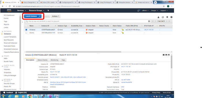
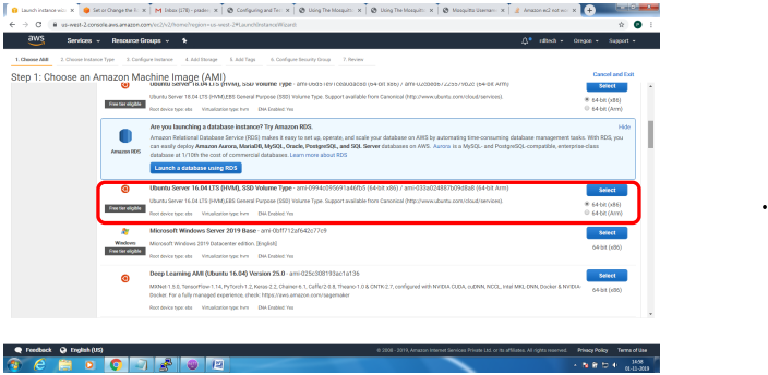
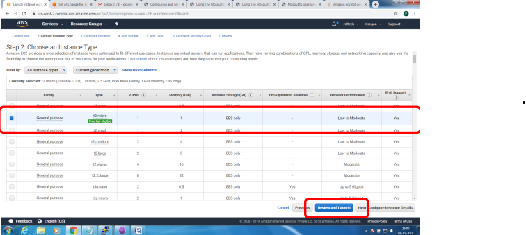
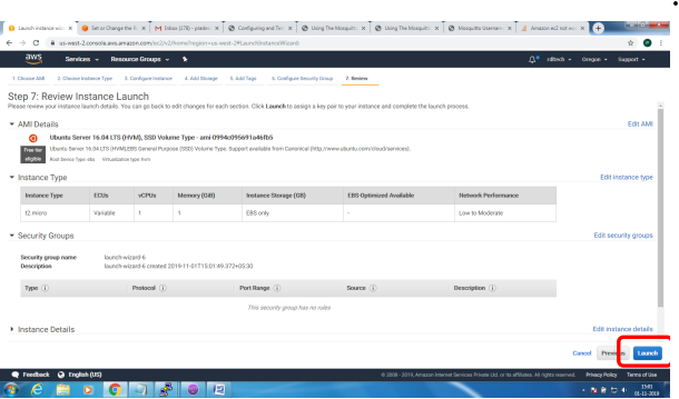
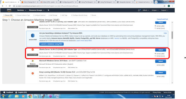
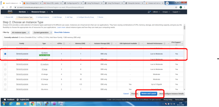
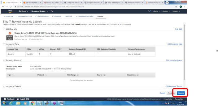
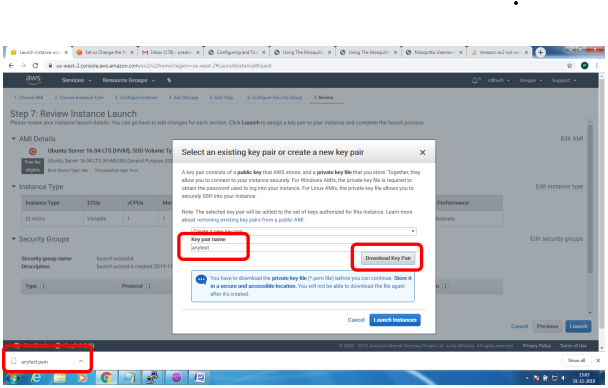
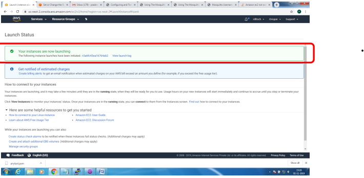
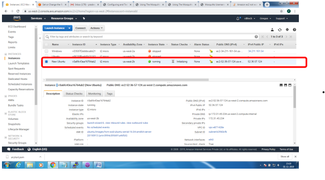
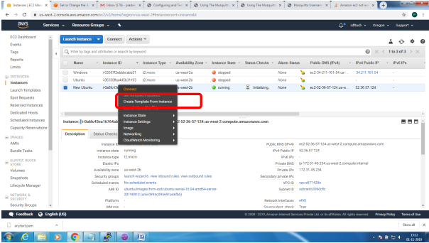
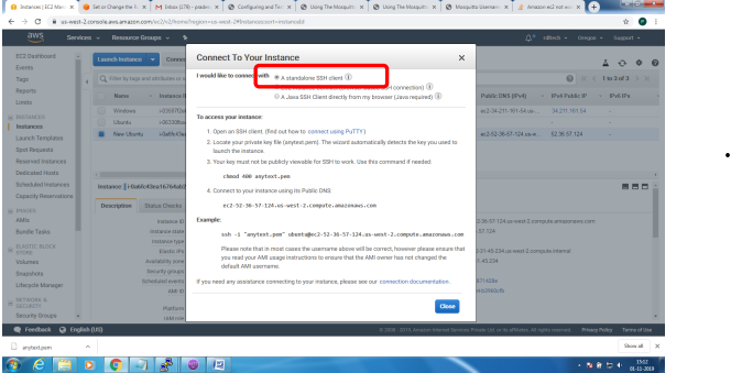
1. Bring up EC2 Linux System
2. Install mosquitto on the above system
Bring up EC2 Linux System
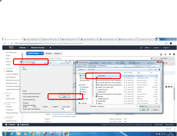
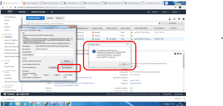
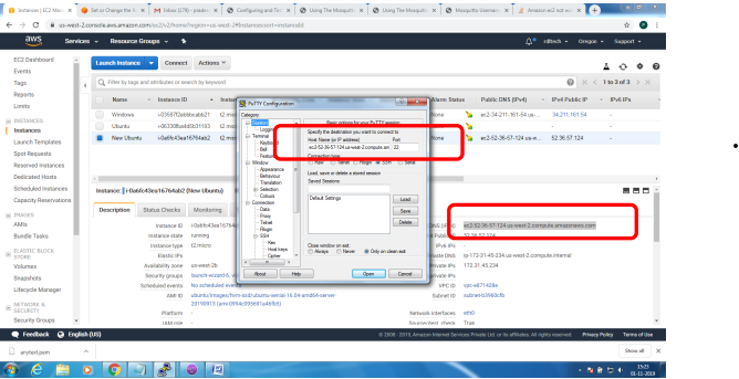
Installation of mosquitto on linux system
Follow the below steps to install mosquitto
- sudo apt-add-repository ppa:mosquitto-dev/mosquitto-ppa
- sudo apt-get update
- sudo apt-get install mosquitto
- sudo apt-get install mosquitto-clients
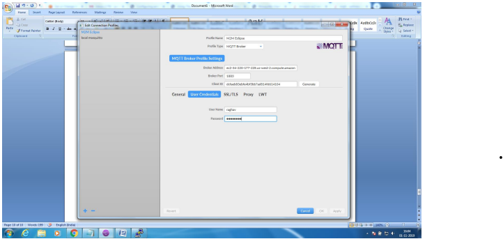
Follow the below steps to Enable user authentication
- Create a txt file in the following format
- Username:Password
- Issue the following commands to add certificate to this file
- mosquitto_passwd -U passwordfile (text file name)
- Copy this file to /etc/mosquitto
Open mosquiito.conf and add these 2 lines to enable user authentication
allow_anonymous false
password_file etc\mosquitto\passwords.txt
Restart the broker to absorb the changes
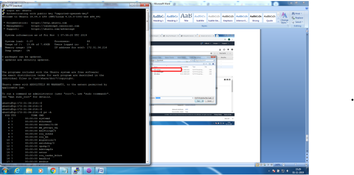
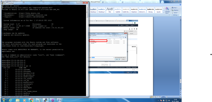
ubuntu@ip-172-31-36-216:~$ mosquitto -v
1572603369: mosquitto version 1.6.7 starting
1572603369: Using default config.
1572603369: Opening ipv4 listen socket on port 1883.
Error: Address already in use
To resolve this
ps –ef | grep mosquitto
kill -9 pid
mosquitto_sub -t '$SYS/#' –v
or
root@ip-172-31-36-216:/home/ubuntu# mosquitto
1572603616: mosquitto version 1.6.7 starting
1572603616: Using default config.
1572603616: Opening ipv4 listen socket on port 1883.
1572603616: Opening ipv6 listen socket on port 1883.
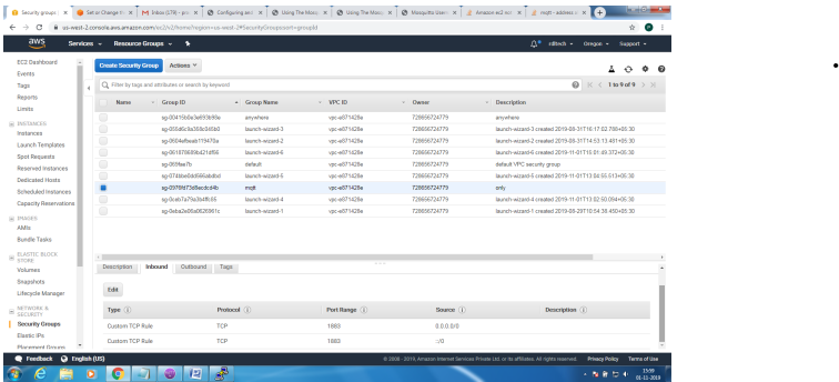
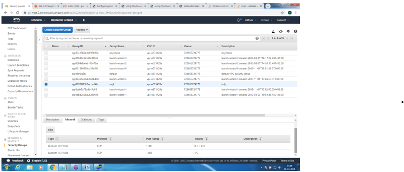
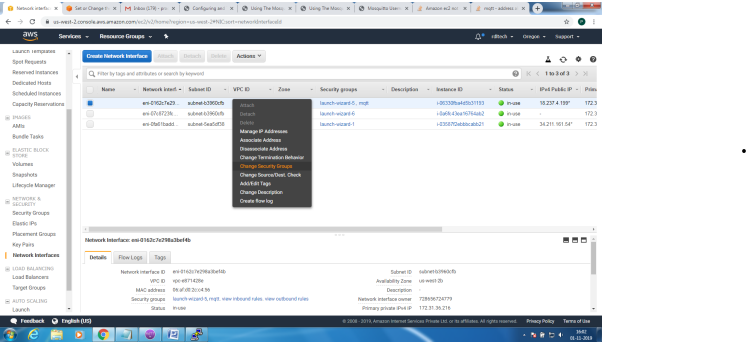
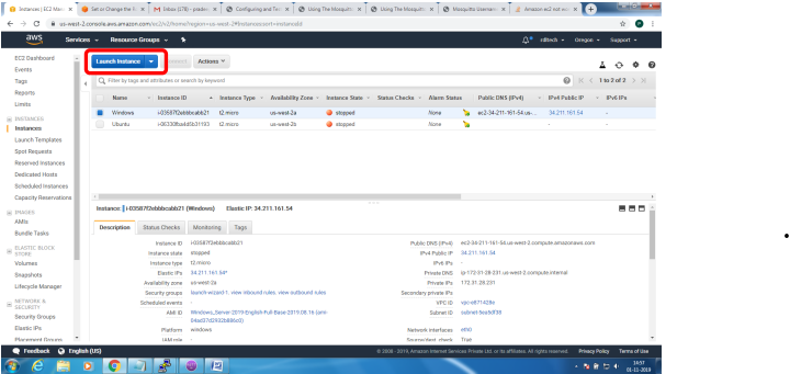
To enable Message flow on to AWS ES2 system, follow the below steps
Create Security Group to allow TCP/1883 traffic in the inbound direction
Mosquitto SSL Configuration -MQTT TLS Security
Server Side:
Openssl tool is used to generate the required keys and certificats for both the server and client
Issue the following commands in sequence and make changes to the mosquitto.conf on the server
for the changes to take effect
1. openssl genrsa -des3 -out ca.key 2048
2. openssl req -new -x509 -days 1826 -key ca.key -out ca.crt
3. openssl genrsa -out server.key 2048
4. openssl req -new -out server.csr -key server.key
5. openssl x509 -req -in server.csr -CA ca.crt -CAkey ca.key -CAcreateserial -out
server.crt -days 360
The directory file listing would look similar to the below
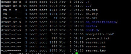
Copy the ca.crt, server.crt and server.key file to /etc/mosquitto/cert folder
Make the following changes to the mosquitto.conf file
Add the following lines
Port 8883
Cafile /etc/mosquitto/certs/ca.crt
Keyfile /etc/mosquitto/certs/server.key
Certfile /etc/mosquitto/certs/server.crt
Most important step is to copy the ca.crt on to the client system.
Incase its get challenging to transfer this file, as it would from AWS EC2 environment. Please use
notepad+ (not plain notepad) to copy paste the certificate contents
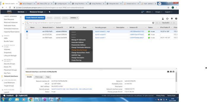
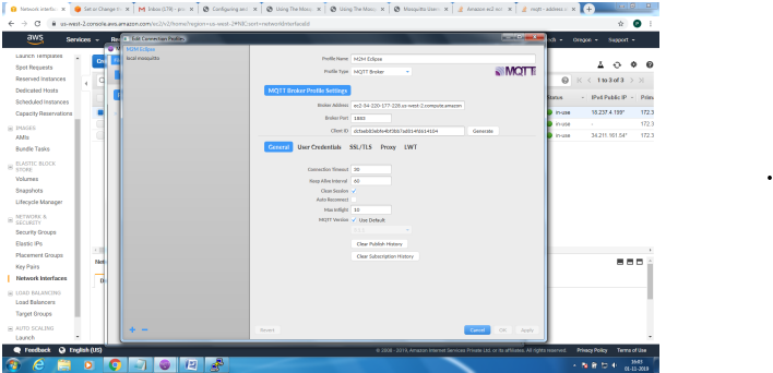
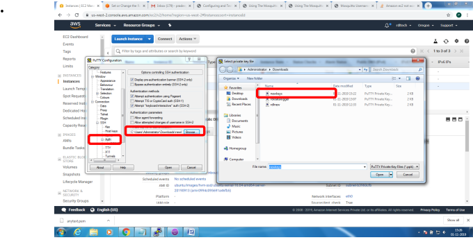
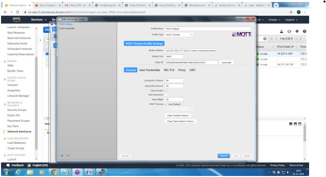
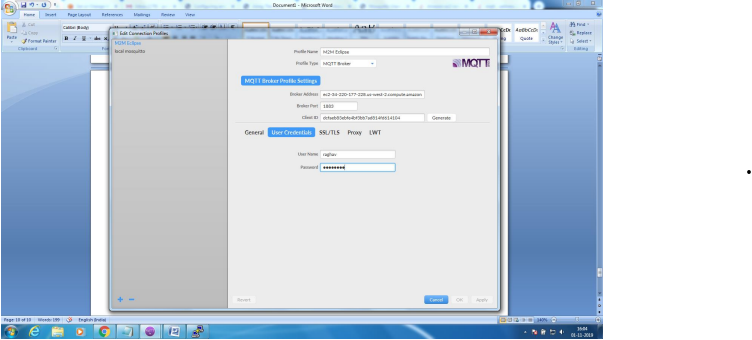
Client Side: Configure the MQTT Client with the broker address, enable SSL and point to the ca.crt
file and connect for application
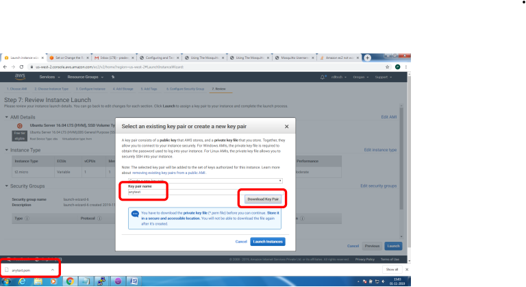
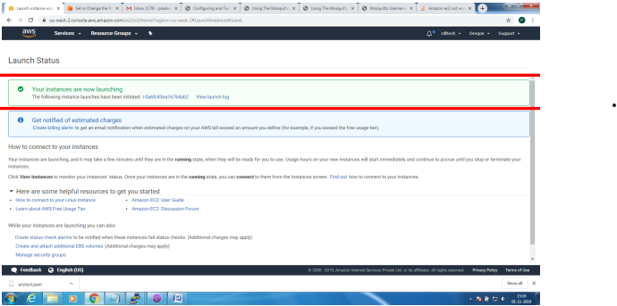
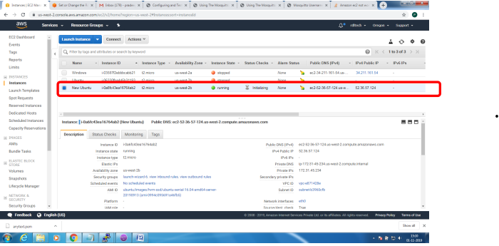
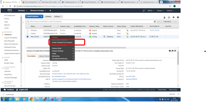
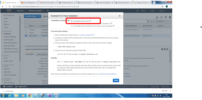
Steps to configure and bring up Mosquitto MQTT Broker on AWS EC2/Linux
Mainly 2 steps
1. Bring up EC2 Linux System
2. Install mosquitto on the above system
Bring up EC2 Linux System
Installation of mosquitto on linux system
Follow the below steps to install mosquitto
- sudo apt-add-repository ppa:mosquitto-dev/mosquitto-ppa
- sudo apt-get update
- sudo apt-get install mosquitto
- sudo apt-get install mosquitto-clients
Follow the below steps to Enable user authentication
- Create a txt file in the following format
- Username:Password
- Issue the following commands to add certificate to this file
- mosquitto_passwd -U passwordfile (text file name)
- Copy this file to /etc/mosquitto
Open mosquiito.conf and add these 2 lines to enable user authentication
allow_anonymous false
password_file etc\mosquitto\passwords.txt
Restart the broker to absorb the changes
ubuntu@ip-172-31-36-216:~$ mosquitto -v
1572603369: mosquitto version 1.6.7 starting
1572603369: Using default config.
1572603369: Opening ipv4 listen socket on port 1883.
Error: Address already in use
To resolve this
ps –ef | grep mosquitto
kill -9 pid
mosquitto_sub -t '$SYS/#' –v
or
root@ip-172-31-36-216:/home/ubuntu# mosquitto
1572603616: mosquitto version 1.6.7 starting
1572603616: Using default config.
1572603616: Opening ipv4 listen socket on port 1883.
1572603616: Opening ipv6 listen socket on port 1883.
To enable Message flow on to AWS ES2 system, follow the below steps
Create Security Group to allow TCP/1883 traffic in the inbound direction