Digital Input (High/Low)
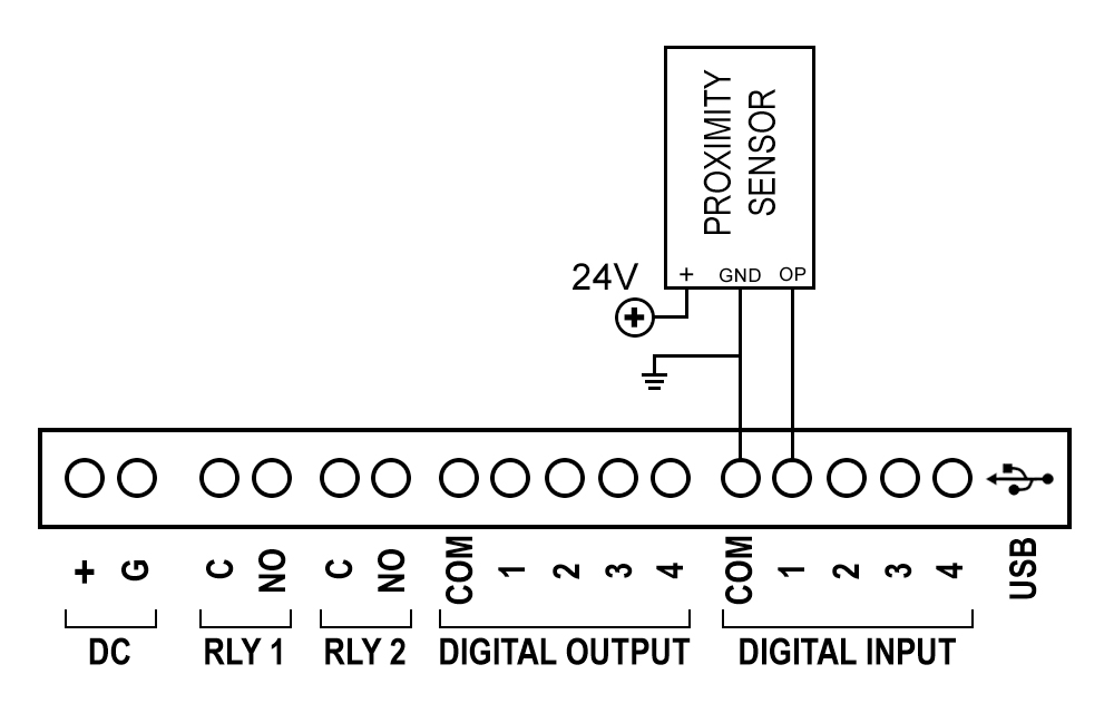
• This program uses the Cloud_PLC library to read the state of the digital input IN1.
• It continuously checks if IN1 is HIGH or LOW and prints "HIGH" or "LOW" to the Serial Monitor accordingly, with a 2-second delay
between each check.
• The setup function initializes the Cloud_PLC system and serial communication.
• The loop function handles the repeated state checking and reporting.
Wiring Diagram
Code
#include "Cloud_PLC.h"  //Include the header file for Cloud_PLC library
		  void setup()
		  {
  Serial.begin(115200);        //Initialize serial communication at 115200 baud rate
  Cloud_PLC_initialisation();  //Call the initialization function for Cloud_PLC
  }

  void loop()

 {  // Check the digital input state of IN1
    Serial.print("Digital input: ");

  if (Cloud_PLC_Digital_Read(DI4) == HIGH) //input channel, DI1, DI2, D13, D14,
  {
    Serial.println("HIGH");      // Print "ON" to the Serial Monitor if DI4 is HIGH
    delay(2000);
  }
else
  {
    Serial.println("LOW");       // Print "OFF" to the Serial Monitor
    delay(2000);                  // Wait for 2000 milliseconds (2 seconds)
  }
}
Note
![]() Libraries, User Manuals and Installation guides look into the download section.
Libraries, User Manuals and Installation guides look into the download section.
![]() Install the Cloud PLC libraries(cloudplc.h) before getting start with coding. Download
Install the Cloud PLC libraries(cloudplc.h) before getting start with coding. Download
![]() Above download link, you will find all the IO functionalities included in the Cloud PLC library.
Above download link, you will find all the IO functionalities included in the Cloud PLC library.
![]() In the Arduino IDE, go to the Boards Manager, select the ESP32 board, ensure that you have selected the board version is 1.0.4 and select the com port of the device.
In the Arduino IDE, go to the Boards Manager, select the ESP32 board, ensure that you have selected the board version is 1.0.4 and select the com port of the device.
Video
Counter Input
• This program counts the number of times the digital input pin IN4 transitions from LOW to HIGH using an interrupt service routine (ISR) and debouncing.
• When IN4 goes HIGH, the ISR increments a counter and prints the count to the Serial Monitor, ensuring accurate counting by checking that at least 250 milliseconds have passed since the last count.
• The setup function initializes the Cloud_PLC system and sets up the interrupt, while the loop function remains empty as the main functionality is handled by the ISR(interrupt service routine).
Code
#include "Cloud_PLC.h"
const int digitalPin = DI4;  // the value can be assigned as your preference DI1, DI2, DI3, DI4.
volatile int count = 0;      //initialize count as 0
int interval = 250;          //debounce time
long button_time = 0;
long LAST_COUNT = 0;
void IRAM_ATTR Ext_INT4_ISR()
{  // function for
  button_time = millis();        // Assign millis() to button_time (millis() Returns the number of milliseconds since the device began running the current program)
  if (button_time - LAST_COUNT > interval)
 {
    if (digitalRead(digitalPin) == HIGH)
 {
      LAST_COUNT = button_time;
      count++;
     Serial.print("Proximity sensor count: ");
      Serial.println(count);
    }
  }
}
void setup()
{
  Cloud_PLC_initialisation();  // Config digital pins DI1, DI2, DI3 and DI4 as INPUT
  Serial.begin(9600);
  attachInterrupt(digitalPinToInterrupt(digitalPin), Ext_INT4_ISR, RISING);
}
void loop()
{
  // put your main code here, to run repeatedly: }
}
Note
![]() Libraries, User Manuals and Installation guides look into the download section.
Libraries, User Manuals and Installation guides look into the download section.
![]() Install the Cloud PLC libraries(cloudplc.h) before getting start with coding. Download
Install the Cloud PLC libraries(cloudplc.h) before getting start with coding. Download
![]() Above download link, you will find all the IO functionalities included in the Cloud PLC library.
Above download link, you will find all the IO functionalities included in the Cloud PLC library.
![]() In the Arduino IDE, go to the Boards Manager, select the ESP32 board, ensure that you have selected the board version is 1.0.4 and select the com port of the device.
In the Arduino IDE, go to the Boards Manager, select the ESP32 board, ensure that you have selected the board version is 1.0.4 and select the com port of the device.
Video
Digital Output (High/Low)
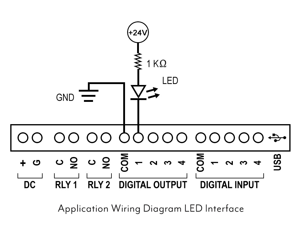
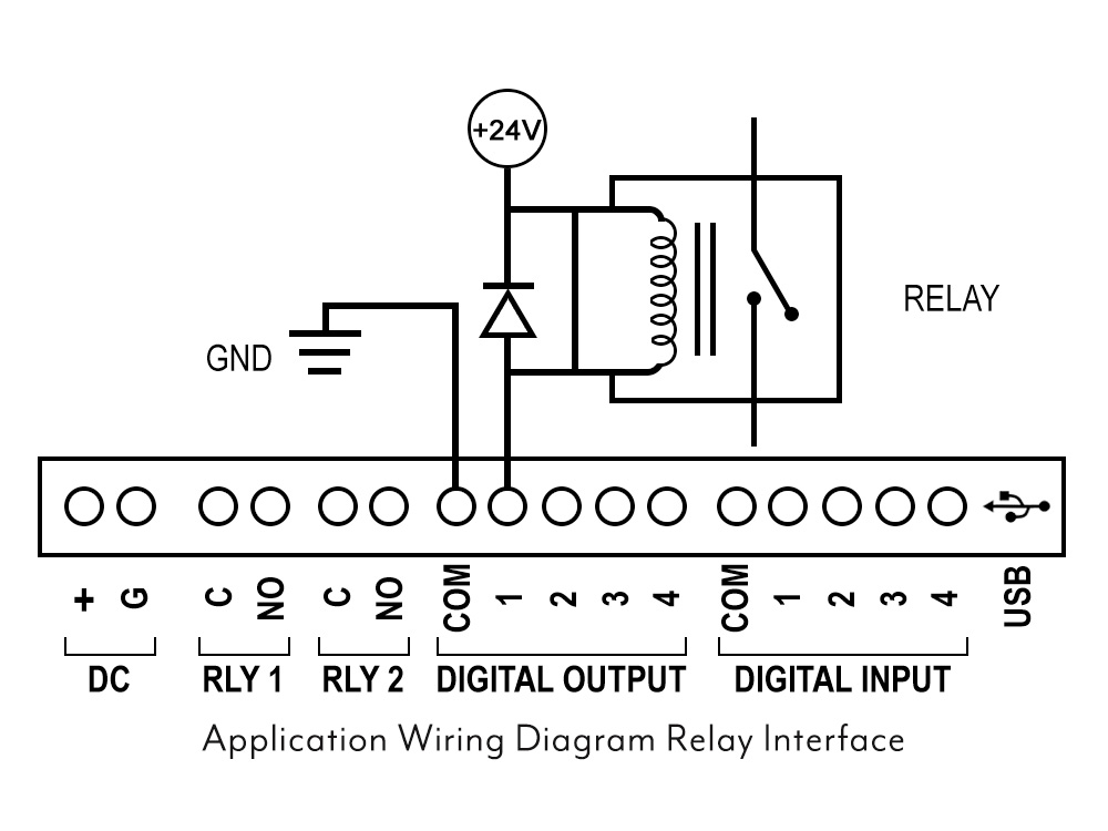
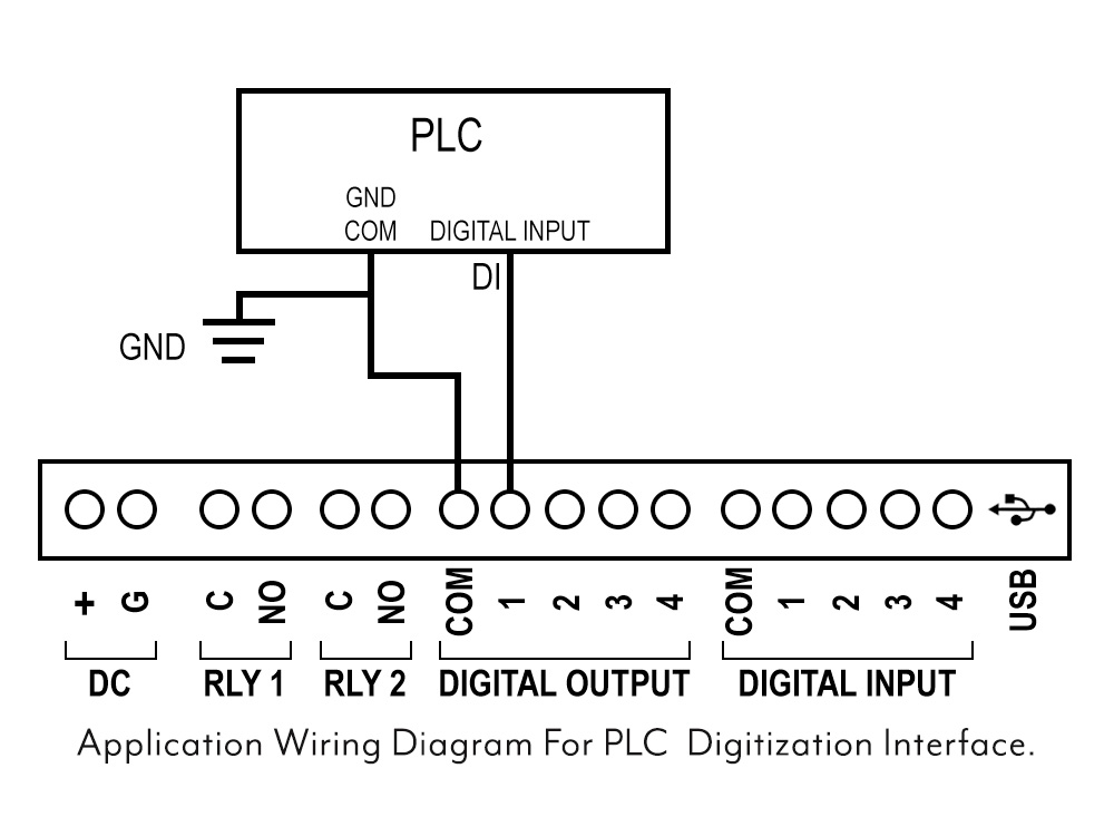
• This program uses the Cloud_PLC library to control four digital output pins (DO1, DO2, DO3, DO4).
• In the setup function, it initializes the Cloud_PLC system.
• The loop function continuously turns all four outputs HIGH for 4 seconds, then LOW for 2 seconds, effectively blinking connected LEDs or
devices on and off in this pattern.
Wiring Diagram
Code
	#include "Cloud_PLC.h"  // This line includes  CloudPLC functions.

void setup()
{
  Cloud_PLC_initialisation();  // Configure digital pins DO1, DO2, DO3, and DO4 as OUTPUT
}

void loop()
{
  Cloud_PLC_Digital_Write(DO1, HIGH); // GREEN ON
  delay(3500);
  Cloud_PLC_Digital_Write(DO1, LOW); //  GREEN OFF
  delay(3500);
  Cloud_PLC_Digital_Write(DO2, HIGH); //  YELLOW ON
  delay(3500);
  Cloud_PLC_Digital_Write(DO2, LOW); //  YELLOW OFF
  delay(3500);
  Cloud_PLC_Digital_Write(DO3, HIGH); // RED ON
  delay(3500);
  Cloud_PLC_Digital_Write(DO3, LOW); // RED OFF
  delay(3500);
}
Note
![]() Libraries, User Manuals and Installation guides look into the download section.
Libraries, User Manuals and Installation guides look into the download section.
![]() Install the Cloud PLC libraries(cloudplc.h) before getting start with coding. Download
Install the Cloud PLC libraries(cloudplc.h) before getting start with coding. Download
![]() Above download link, you will find all the IO functionalities included in the Cloud PLC library.
Above download link, you will find all the IO functionalities included in the Cloud PLC library.
![]() In the Arduino IDE, go to the Boards Manager, select the ESP32 board, ensure that you have selected the board version is 1.0.4 and select the com port of the device.
In the Arduino IDE, go to the Boards Manager, select the ESP32 board, ensure that you have selected the board version is 1.0.4 and select the com port of the device.
Video
Digital Output PWM
• This program uses the Cloud_PLC library to control the brightness of an LED connected to pin 12 using PWM (Pulse Width Modulation).
• In the setup function, it initializes the PWM settings with a frequency of 5000 Hz and an 8-bit resolution.
• The loop function continuously increases and then decreases the LED brightness in a smooth transition by adjusting the PWM duty cycle.
Wiring Diagram


Code
#include"Cloud_PLC.h"

// Default PWM properties
int freq = 5000;     // PWM frequency in Hz
int ledChannel = 0;  // PWM channel (0-15)
int resolution = 8;  // PWM resolution (8 bits, 0-255)


void Cloud_PLC_PWM(int frequency, int pwmResolution)
 {
  freq = frequency;
  resolution = pwmResolution;

  ledcSetup(ledChannel, freq, resolution);
  ledcAttachPin(NETWORK_LED, ledChannel);//PIN NO 12
}

// Function to increase brightness
void increaseBrightness()
{
  for (int dutyCycle = 0; dutyCycle <= 255; dutyCycle++)
{
    ledcWrite(ledChannel, dutyCycle);
    delay(15);
  }
}

// Function to decrease brightness
void decreaseBrightness()
{
  for (int dutyCycle = 255; dutyCycle >= 0; dutyCycle--)
 {
    ledcWrite(ledChannel, dutyCycle);
    delay(15);
  }
}

void setup()
 {
  Cloud_PLC_PWM(freq, resolution); // Call Cloud_PLC_PWM with default values
}

void loop()
{
  increaseBrightness();
  decreaseBrightness();
}
Note
![]() Libraries, User Manuals and Installation guides look into the download section.
Libraries, User Manuals and Installation guides look into the download section.
![]() Install the Cloud PLC libraries(cloudplc.h) before getting start with coding. Download
Install the Cloud PLC libraries(cloudplc.h) before getting start with coding. Download
![]() Above download link, you will find all the IO functionalities included in the Cloud PLC library.
Above download link, you will find all the IO functionalities included in the Cloud PLC library.
![]() In the Arduino IDE, go to the Boards Manager, select the ESP32 board, ensure that you have selected the board version is 1.0.4 and select the com port of the device.
In the Arduino IDE, go to the Boards Manager, select the ESP32 board, ensure that you have selected the board version is 1.0.4 and select the com port of the device.
Video
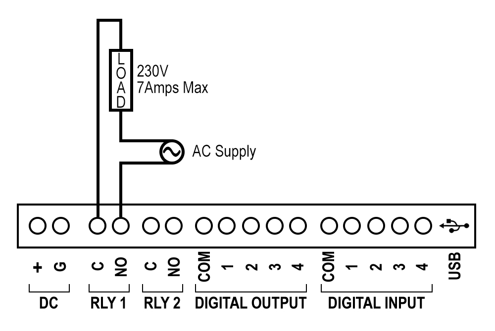
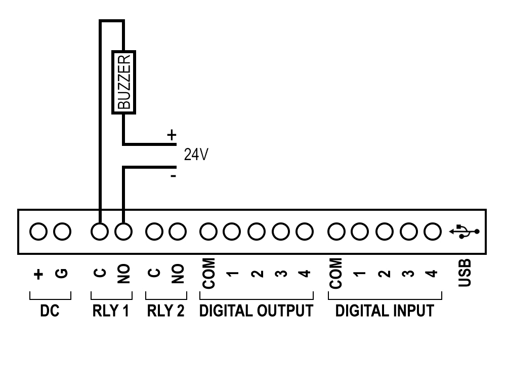
Relay
• This program uses the Cloud_PLC library to control two relay channels.
• In the setup function, it initializes the Cloud_PLC system.
• The loop function alternately turns relay channel 0 and relay channel 1 on and off with a 1-second delay between each state change, continuously cycling through these actions.
Wiring Diagram
Code
#include "Cloud_PLC.h"   // This line includes the necessary library for using Cloud PLC functions.

  void setup()
 {
  Cloud_PLC_initialisation();
}
  void loop()
{
  Cloud_PLC_Relay_state(0, HIGH);  //Relay1 channel, State is ON
  delay(1000);
  Cloud_PLC_Relay_state(0, LOW);  // Relay1 is OFF
  delay(1000);
  Cloud_PLC_Relay_state(1, HIGH);  // Relay2 is ON
  delay(1000);
  Cloud_PLC_Relay_state(1, LOW);  // Relay2 is OFF
  delay(1000);
}
Note
![]() Libraries, User Manuals and Installation guides look into the download section.
Libraries, User Manuals and Installation guides look into the download section.
![]() Install the Cloud PLC libraries(cloudplc.h) before getting start with coding. Download
Install the Cloud PLC libraries(cloudplc.h) before getting start with coding. Download
![]() Above download link, you will find all the IO functionalities included in the Cloud PLC library.
Above download link, you will find all the IO functionalities included in the Cloud PLC library.
![]() In the Arduino IDE, go to the Boards Manager, select the ESP32 board, ensure that you have selected the board version is 1.0.4 and select the com port of the device.
In the Arduino IDE, go to the Boards Manager, select the ESP32 board, ensure that you have selected the board version is 1.0.4 and select the com port of the device.
Video
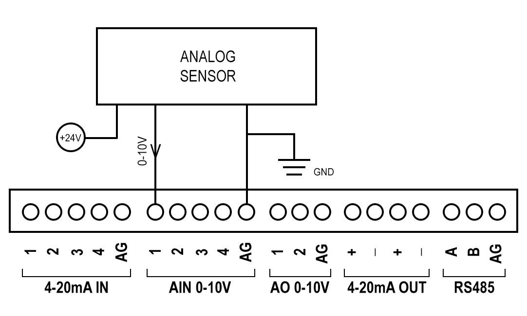
Analog Input (ADC 0-10V)
• This program uses the Cloud_PLC library to read analog values from an ADC (Analog-to-Digital Converter) channel.
• In the setup function, it initializes serial communication at 115200 bps and configures the ADC.
• The loop function continuously reads the analog value from ADC channel 0, prints it to the Serial Monitor and waits for 2 seconds before repeating the process.
Wiring Diagram
Code
#include <Wire.h>
#include <Nanoshield_ADC.h>
#include "MCP23008.h"
MCP23008 MCP(0x20);
Nanoshield_ADC adc;
int channel = 0;
void setup()
{
  Serial.begin(9600);
  Serial.print("16-bit ADC Nanoshield Test - Read voltage (channel A");
  Serial.print(channel);
  Serial.println(")");
  adc.begin();
  Serial.begin(115200);
  Serial.println(__FILE__);
  Serial.print("MCP23008_LIB_VERSION: ");
  Serial.println(MCP23008_LIB_VERSION);
  Serial.println();
  delay(100);
  Wire.begin();
  MCP.begin();
  pinMode(15, INPUT);
  pinMode(15, OUTPUT); //  use pin8 to read back MCP.pin0
  MCP.pinMode8(0x00);    //  0 = output,  1 = input
  MCP.write8(0xFF);
  Wire.setClock(100000);
 // Read the 4-20mA  io expander channel should be high(1)
  //  MCP.write1(0, 1);4-20mA
  //  MCP.write1(1, 1);// For reading 4-20mA uncomment the commended portion
  //  MCP.write1(2, 1);
  //  MCP.write1(3, 1);
  //  MCP.write1(4, 1);
  //  MCP.write1(5, 1);
  //  MCP.write1(6, 1);
  //  MCP.write1(7, 1);
// Read the ADC io expander channel should be low
  MCP.write1(0, 0);//ADC
  MCP.write1(1, 0);
  MCP.write1(2, 0);
  MCP.write1(3, 0);
  MCP.write1(4, 0);
  MCP.write1(5, 0);
  MCP.write1(6, 0);
  MCP.write1(7, 0);
}

void loop()
{
  //  Serial.print(adc.read4to20mA(0), 6);// For reading 4-20mA uncomment the commended portion
  //  Serial.print(" mA | ");
  //  Serial.print(adc.read4to20mA(1), 6);
  //  Serial.print(" mA | ");
  //  Serial.print(adc.read4to20mA(2), 6);
  //  Serial.print(" mA | ");
  //  Serial.print(adc.read4to20mA(3), 6);
  //  Serial.println(" mA");
  //  delay(1000);
  Serial.print(adc.readVoltage(0));
  Serial.print("  V |  ");
  Serial.print(adc.readVoltage(1));
  Serial.print("  V |  ");
  Serial.print(adc.readVoltage(2));
  Serial.print("  V |  ");
  Serial.print(adc.readVoltage(3));
  Serial.println("  V |  ");
  delay(1000);
}
This code initializes an ESP32 to interact with two peripherals: an MCP23008 I/O expander and a Nanoshield ADC module. The setup() configures the I/O expander to control digital pins (output as high or low) and prepares the ADC module to read voltages. In the loop(), the code reads and prints the voltages from the ADC's four input channels to the serial monitor every second. Commented sections hint at alternative functionality for reading 4-20mA signals.
Note
![]() Libraries, User Manuals and Installation guides look into the download section.
Libraries, User Manuals and Installation guides look into the download section.
![]() Install the Cloud PLC libraries(cloudplc.h) before getting start with coding. Download
Install the Cloud PLC libraries(cloudplc.h) before getting start with coding. Download
![]() Above download link, you will find all the IO functionalities included in the Cloud PLC library.
Above download link, you will find all the IO functionalities included in the Cloud PLC library.
![]() In the Arduino IDE, go to the Boards Manager, select the ESP32 board, ensure that you have selected the board version is 1.0.4 and select the com port of the device.
In the Arduino IDE, go to the Boards Manager, select the ESP32 board, ensure that you have selected the board version is 1.0.4 and select the com port of the device.
Video
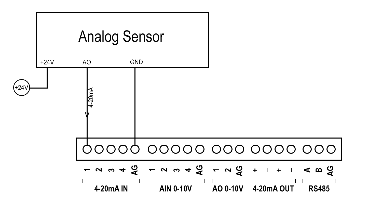
Analog Input (4-20mA)
• This program uses the Cloud_PLC library to read 4-20 mA input values from four channels
• In the setup function, it initializes serial communication and configures the Cloud PLC to read 4-20 mA inputs.
• The loop function iterates through the four input channels, prints each reading with six decimal places to the Serial Monitor, and adds a 200 ms delay between readings.
• After printing all four values on the same line, it moves to the next line
Wiring Diagram
Code
#include <Wire.h>
#include <Nanoshield_ADC.h>

#include "MCP23008.h"


MCP23008 MCP(0x20);

Nanoshield_ADC adc;
int channel = 0;

void setup()
{
  Serial.begin(9600);
  Serial.print("16-bit ADC Nanoshield Test - Read voltage (channel A");
  Serial.print(channel);
  Serial.println(")");
  adc.begin();
  Serial.begin(115200);
  Serial.println(__FILE__);
  Serial.print("MCP23008_LIB_VERSION: ");
  Serial.println(MCP23008_LIB_VERSION);
  Serial.println();
  delay(100);

  Wire.begin();

  MCP.begin();

  pinMode(15, INPUT);
  pinMode(15, OUTPUT); //  use pin8 to read back MCP.pin0

  MCP.pinMode8(0x00);    //  0 = output,  1 = input
  MCP.write8(0xFF);
  Wire.setClock(100000);
 // Read the 4-20mA  io expander channel should be high(1)
  //  MCP.write1(0, 1);4-20mA
  //  MCP.write1(1, 1);// For reading 4-20mA uncomment the commended portion
  //  MCP.write1(2, 1);
  //  MCP.write1(3, 1);
  //  MCP.write1(4, 1);
  //  MCP.write1(5, 1);
  //  MCP.write1(6, 1);
  //  MCP.write1(7, 1);
// Read the ADC io expander channel should be low
  MCP.write1(0, 0);//ADC
  MCP.write1(1, 0);
  MCP.write1(2, 0);
  MCP.write1(3, 0);
  MCP.write1(4, 0);
  MCP.write1(5, 0);
  MCP.write1(6, 0);
  MCP.write1(7, 0);
}

void loop()
{
  //  Serial.print(adc.read4to20mA(0), 6);// For reading 4-20mA uncomment the commended portion
  //  Serial.print(" mA | ");
  //  Serial.print(adc.read4to20mA(1), 6);
  //  Serial.print(" mA | ");
  //  Serial.print(adc.read4to20mA(2), 6);
  //  Serial.print(" mA | ");
  //  Serial.print(adc.read4to20mA(3), 6);
  //  Serial.println(" mA");
  //  delay(1000);
  Serial.print(adc.readVoltage(0));
  Serial.print("  V |  ");
  Serial.print(adc.readVoltage(1));
  Serial.print("  V |  ");
  Serial.print(adc.readVoltage(2));
  Serial.print("  V |  ");
  Serial.print(adc.readVoltage(3));
  Serial.println("  V |  ");
  delay(1000);


}
This code initializes an ESP32 to interact with two peripherals: an MCP23008 I/O expander and a Nanoshield ADC module. The setup() configures the I/O expander to control digital pins (output as high or low) and prepares the ADC module to read voltages. In the loop(), the code reads and prints the voltages from the ADC's four input channels to the serial monitor every second. Commented sections hint at alternative functionality for reading 4-20mA signals.
Note
![]() Libraries, User Manuals and Installation guides look into the download section.
Libraries, User Manuals and Installation guides look into the download section.
![]() Install the Cloud PLC libraries(cloudplc.h) before getting start with coding. Download
Install the Cloud PLC libraries(cloudplc.h) before getting start with coding. Download
![]() Above download link, you will find all the IO functionalities included in the Cloud PLC library.
Above download link, you will find all the IO functionalities included in the Cloud PLC library.
![]() In the Arduino IDE, go to the Boards Manager, select the ESP32 board, ensure that you have selected the board version is 1.0.4 and select the com port of the device.
In the Arduino IDE, go to the Boards Manager, select the ESP32 board, ensure that you have selected the board version is 1.0.4 and select the com port of the device.
Video
Analog Output (0-10V)
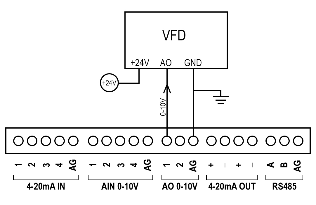
• This program initializes the Cloud_PLC library and sets up serial communication at 115200 bps.
• In the setup function, it configures the DAC (Digital-to-Analog Converter) and sets specific output values for two DAC channels: 2048 (5V)
for channel A and 4095 (10V) for channel B.
• The loop function simply waits for 1 second in each iteration without additional functionality.
Wiring Diagram
Code
#include <Cloud_PLC.h>

void setup(void)
 {
  // Initialize Serial communication
  Serial.begin(115200);
  while (!Serial)
    delay(10);  // will pause Zero, Leonardo, etc until serial console opens

    Serial.println("Cloud PLC DAC TEST");

  // cloud_PLC_initialize
  Cloud_PLC_initDAC();

  // Set DAC values
  setDACValue(MCP4728_CHANNEL_A, 2048);// channel 1  5V will be scaled from  0-2048
  setDACValue(MCP4728_CHANNEL_B, 4095);// channel 2 10V will be scaled from 0-4095
  // You can add more calls to setDACValue for other channels if needed
}

void loop()
 {
  // Your loop code here
  delay(1000);
}
Note
![]() Libraries, User Manuals and Installation guides look into the download section.
Libraries, User Manuals and Installation guides look into the download section.
![]() Install the Cloud PLC libraries(cloudplc.h) before getting start with coding. Download
Install the Cloud PLC libraries(cloudplc.h) before getting start with coding. Download
![]() Above download link, you will find all the IO functionalities included in the Cloud PLC library.
Above download link, you will find all the IO functionalities included in the Cloud PLC library.
![]() In the Arduino IDE, go to the Boards Manager, select the ESP32 board, ensure that you have selected the board version is 1.0.4 and select the com port of the device.
In the Arduino IDE, go to the Boards Manager, select the ESP32 board, ensure that you have selected the board version is 1.0.4 and select the com port of the device.
Video
Analog Output (4-20mA)
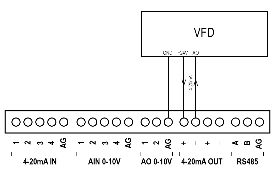
• This program initializes serial communication at 115200 bps and sets up the Cloud_PLC library to handle 4-20 mA outputs.
• In the setup function, it configures the 4-20 mA output channels and sets channel C to 20 mA and channel D to 4 mA.
• The loop function simply introduces a 1-second delay without additional functionality.
Wiring Diagram
Code
#include <Cloud_PLC.h>
void setup(void)
{
  // Initialize Serial communication
  Serial.begin(115200);
  while (!Serial)
    delay(10);  // will pause Zero, Leonardo, etc until serial console opens
  Serial.println("Cloud PLC 4-20mA TEST");
  // cloud_PLC_initialize
  Cloud_PLC_4_20output();
  // Set DAC values
  Cloud_PLC_set4_20output(MCP4728_CHANNEL_C, 4095);  // channel 1 20mA
  Cloud_PLC_set4_20output(MCP4728_CHANNEL_D, 0);     //channel 2 4mA
  // You can add more calls to Cloud_PLC_set4_20output for other channels if needed
}
void loop()
{

  delay(1000 ); // Your loop code here
}
Note
![]() Libraries, User Manuals and Installation guides look into the download section.
Libraries, User Manuals and Installation guides look into the download section.
![]() Install the Cloud PLC libraries(cloudplc.h) before getting start with coding. Download
Install the Cloud PLC libraries(cloudplc.h) before getting start with coding. Download
![]() Above download link, you will find all the IO functionalities included in the Cloud PLC library.
Above download link, you will find all the IO functionalities included in the Cloud PLC library.
![]() In the Arduino IDE, go to the Boards Manager, select the ESP32 board, ensure that you have selected the board version is 1.0.4 and select the com port of the device.
In the Arduino IDE, go to the Boards Manager, select the ESP32 board, ensure that you have selected the board version is 1.0.4 and select the com port of the device.
Video
Modbus RS485 (Master)
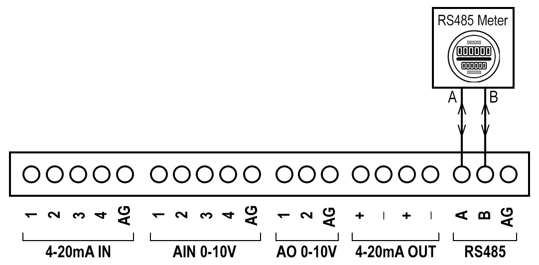
• This program uses the ModbusMaster library to read data from a Modbus slave device.
• In the setup function, it initializes serial communication for debugging and Modbus communication over Serial2.
• The loop function reads a holding register from the Modbus slave with a specified address and prints the value to the Serial Monitor if the
read operation is successful.
• It waits for 5 seconds before performing the next read operation.
Wiring Diagram
Code
#include <ModbusMaster.h>

int value = 0;
bool status;
ModbusMaster node;

void setup()
{
  // Initialize Serial for debugging output
  Serial.begin(9600);

  // Initialize Serial2 for Modbus communication
  // Communication parameters: 9600 baud rate, no parity, 8 data bits, 1 stop bit
  Serial2.begin(9600);

  // Begin Modbus communication over Serial2
  node.begin(Serial2);
}

void loop()
 {
  // Read holding registers from the Modbus slave
  // Parameters: (slave ID, starting address, number of registers)
  // Example: read 1 register starting from address 1 of slave device with ID 1
  status = node.readHoldingRegisters(1, 1, 1);

  // Check if the read operation was successful
  if (status == node.ku8MBSuccess)
{
    // Get the value from the response buffer and print it
    value = node.getResponseBuffer(0);
    Serial.println(value);
  }

  // Delay for 5 seconds before the next read operation
  delay(5000);
}
Note
![]() Libraries, User Manuals and Installation guides look into the download section.
Libraries, User Manuals and Installation guides look into the download section.
![]() Install the Cloud PLC libraries(cloudplc.h) before getting start with coding. Download
Install the Cloud PLC libraries(cloudplc.h) before getting start with coding. Download
![]() Above download link, you will find all the IO functionalities included in the Cloud PLC library.
Above download link, you will find all the IO functionalities included in the Cloud PLC library.
![]() In the Arduino IDE, go to the Boards Manager, select the ESP32 board, ensure that you have selected the board version is 1.0.4 and select the com port of the device.
In the Arduino IDE, go to the Boards Manager, select the ESP32 board, ensure that you have selected the board version is 1.0.4 and select the com port of the device.
Video
Modbus RS485 (Slave)
• This program sets up a Modbus RTU slave device using the ModbusRtu library with communication over Serial2 and controls the RS485
transmission enable pin (TXEN).
• In the setup function, it initializes Serial2 and starts the Modbus slave.
• The loop function continuously polls the Modbus network and updates the data array with predefined values (10, 11, 12, 13) every 10
milliseconds.
Code
#include <ModbusRtu.h>

#define TXEN 4  // Transmission enable pin for RS485

// Data array for Modbus network sharing
uint16_t au16data[4] = { 0, 0, 0, 0 };

// Initialize Modbus slave
Modbus slave(1, Serial2, TXEN);

void setup()
 {
  // Initialize Serial2 for Modbus communication
  Serial2.begin(9600);
  // Start the Modbus slave
  slave.start();
}

void loop()
 {
  slave.poll(au16data, 16);
  au16data[0] = 10;
  au16data[1] = 11;
  au16data[2] = 12;
  au16data[3] = 13;
  delay(10);
}
Note
![]() Libraries, User Manuals and Installation guides look into the download section.
Libraries, User Manuals and Installation guides look into the download section.
![]() Install the Cloud PLC libraries(cloudplc.h) before getting start with coding. Download
Install the Cloud PLC libraries(cloudplc.h) before getting start with coding. Download
![]() Above download link, you will find all the IO functionalities included in the Cloud PLC library.
Above download link, you will find all the IO functionalities included in the Cloud PLC library.
![]() In the Arduino IDE, go to the Boards Manager, select the ESP32 board, ensure that you have selected the board version is 1.0.4 and select the com port of the device.
In the Arduino IDE, go to the Boards Manager, select the ESP32 board, ensure that you have selected the board version is 1.0.4 and select the com port of the device.
Video
Modbus TCP Slave (WiFi) & Master (WiFi)
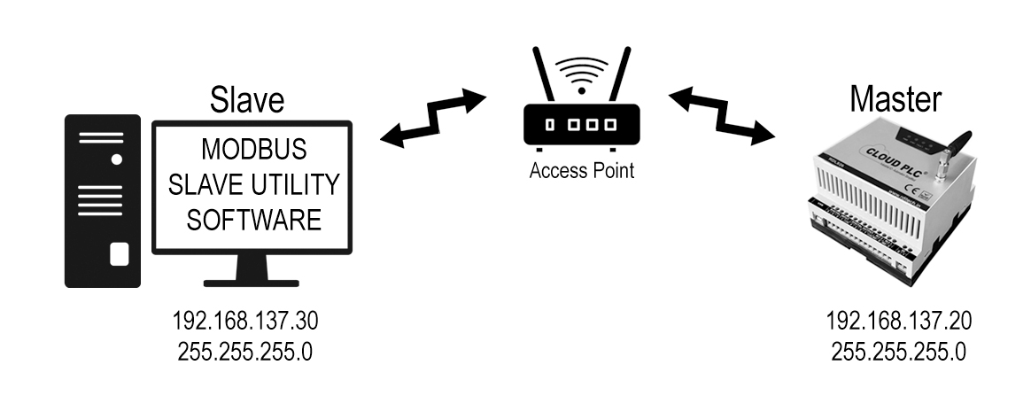
• This code sets up an ESP8266 as a Modbus TCP server using the ModbusIP library.
• It connects to a WiFi network with a static IP configuration and initializes four holding registers with values 0, 11, 22, and 33.
• The server continuously listens for Modbus TCP queries, which are handled in the loop() function.
Wiring Diagram
Modbus TCP Slave (WiFi) Code
#include <WiFiClientSecure.h> //In this code, a Cloud PLC device is configured as a Modbus TCP server,
#include <WiFi.h>
#include <ModbusIP_ESP8266.h>

union {
  uint32_t B32;
  float Float;
} floatb32;

ModbusIP mb;
//mb.Hreg(AC1_LOW_REG, VALUE);
void setup()
{
  // put your setup code here, to run once:
  Serial.begin(115200);
  IPAddress local_IP(192, 168, 137, 30); //Assigning STATIC Ip address
  IPAddress subnet(255, 255, 255, 0);
  IPAddress gateway(192, 168, 137, 1);
  IPAddress primaryDNS(192, 168, 137, 1); // optional
  IPAddress secondaryDNS(192, 168, 137, 1);
  // Connect to WiFi using the configured IP
  delay(500);
  if (!WiFi.config(local_IP, gateway, subnet, primaryDNS, secondaryDNS))
 {
    Serial.println("STA Failed to configure");
  }
  WiFi.begin("your SSID", "your password");
  while (WiFi.status() != WL_CONNECTED)
  {
    delay(500);
    Serial.print('.');
  }
  Serial.println("Connected..!");
  Serial.println(local_IP.toString());
  mb.server();
  mb.addHreg(10,11);// start address 10, total length of register =4
  mb.addHreg(11,12);//2
  mb.addHreg(12,13);//3
  mb.addHreg(13,44);//4
}

void loop()
 {
  // put your main code here, to run repeatedly:
  mb.task(); //mb.Hreg(10,DATA);
  delay(10);
}
Modbus TCP Master (WiFi) Code
		  #ifdef ESP8266
 #include <ESP8266WiFi.h>
#else
 #include <WiFi.h>
#endif
#include <ModbusIP_ESP8266.h>

// Network credentials
const char* ssid = "your SSID";         // Replace with your WiFi SSID
const char* password = "your password"; // Replace with your WiFi password

// Static IP configuration
IPAddress local_IP(192, 168, 137, 20);    // Replace with your desired static IP address
IPAddress gateway(192, 168, 137, 1);       // Replace with your network gateway
IPAddress subnet(255, 255, 255, 0);      // Replace with your network subnet mask

// Modbus server details
IPAddress remote(192, 168, 137, 30); // IP address of the Modbus server
const int START_REG = 10;          // Starting register address
const int NUM_REGS = 4;             // Number of registers to read

ModbusIP mb;  // ModbusIP object

void setup()
 {
  Serial.begin(115200); // Initialize serial communication at 115200 baud

  // Configure static IP
  WiFi.config(local_IP, gateway, subnet);
  WiFi.begin(ssid, password);

  Serial.print("Connecting to WiFi");
  while (WiFi.status() != WL_CONNECTED)
{
    delay(500);
    Serial.print(".");
  }
  Serial.println("");
  Serial.println("WiFi connected");
  Serial.println("IP address: ");
  Serial.println(WiFi.localIP());

  // Initialize Modbus client
  mb.client();
}

void loop()
 {
  static uint16_t results[NUM_REGS]; // Array to store register values
  static uint8_t showCounter = 10;    // Counter to control display frequency

  if (mb.isConnected(remote))
{
    // Read multiple holding registers from the Modbus server
    bool success = mb.readHreg(remote, START_REG, results, NUM_REGS);

    if (success) {
      // Print register values to the serial monitor
      if (--showCounter == 0) {

        Serial.println("Read values:");
        for (int i = 0; i < NUM_REGS; i++) {
          Serial.print("Register ");
          Serial.print(START_REG + i);
          Serial.print(": ");
          Serial.print(results[i]);
          Serial.print(" (0x");
          Serial.print(results[i], HEX);
          Serial.println(")");
        }
        showCounter = 10; // Reset the counter
      }
    } else {
      Serial.println("Failed to read from Modbus server.");
    }
  } else {
    // Attempt to reconnect to the Modbus server
    Serial.println("Attempting to connect to Modbus server...");
    mb.connect(remote);
  }

  mb.task(); // Common local Modbus task
  delay(500); // Delay between readings
}
Note
![]() Libraries, User Manuals and Installation guides look into the download section.
Libraries, User Manuals and Installation guides look into the download section.
![]() Install the Cloud PLC libraries(cloudplc.h) before getting start with coding. Download
Install the Cloud PLC libraries(cloudplc.h) before getting start with coding. Download
![]() Above download link, you will find all the IO functionalities included in the Cloud PLC library.
Above download link, you will find all the IO functionalities included in the Cloud PLC library.
![]() In the Arduino IDE, go to the Boards Manager, select the ESP32 board, ensure that you have selected the board version is 1.0.4 and select the com port of the device.
In the Arduino IDE, go to the Boards Manager, select the ESP32 board, ensure that you have selected the board version is 1.0.4 and select the com port of the device.
FRAM Implimentation
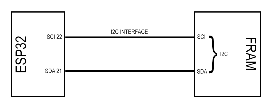
• This program uses the Wire (I2C) and AT24C256 libraries to interface with an AT24C256 EEPROM. In the setup function, it initializes serial
communication and checks if the EEPROM is detected on the I2C bus.
• It then reads an initial message from the EEPROM, writes a new message ("Hello World!") to it, and reads the message again to verify the
write operation.
• The loop function is empty, as the main functionality is handled in setup.
Wiring Diagram
Code
#include <Wire.h>
#include <AT24C256.h>
AT24C256 eeprom;
void setup()
 {
  char message[30];
  char writemessage[] = "Hello World!";
  Serial.begin(9600);
  Wire.begin();
  // Check if EEPROM is detected
  Wire.beginTransmission(0x50);
  if (Wire.endTransmission() != 0)
 {
    Serial.println("EEPROM not detected. Check wiring!");
    while (1); // halt the program
  }
  Serial.println("EEPROM detected.");
  // Read from EEPROM
  for (int i = 0; i < sizeof(message); i++)
 {
    message[i] = eeprom.read(i);
  }
  Serial.print("Initial read: ");
  Serial.println(message);
  // Write to EEPROM
  for (int i = 0; i < sizeof(writemessage); i++)
 {
    eeprom.write(i, writemessage[i]);
  }
  Serial.println("Wrote to EEPROM");
  // Read from EEPROM again
  for (int i = 0; i < sizeof(message); i++)
{
    message[i] = eeprom.read(i);
  }
  Serial.print("Read after write: ");
  Serial.println(message);
}
void loop()
{
  // put your main code here, to run repeatedly:
}
Note
![]() Libraries, User Manuals and Installation guides look into the download section.
Libraries, User Manuals and Installation guides look into the download section.
![]() Install the Cloud PLC libraries(cloudplc.h) before getting start with coding. Download
Install the Cloud PLC libraries(cloudplc.h) before getting start with coding. Download
![]() Above download link, you will find all the IO functionalities included in the Cloud PLC library.
Above download link, you will find all the IO functionalities included in the Cloud PLC library.
![]() In the Arduino IDE, go to the Boards Manager, select the ESP32 board, ensure that you have selected the board version is 1.0.4 and select the com port of the device.
In the Arduino IDE, go to the Boards Manager, select the ESP32 board, ensure that you have selected the board version is 1.0.4 and select the com port of the device.
Video
SD Card with Analog Input Log
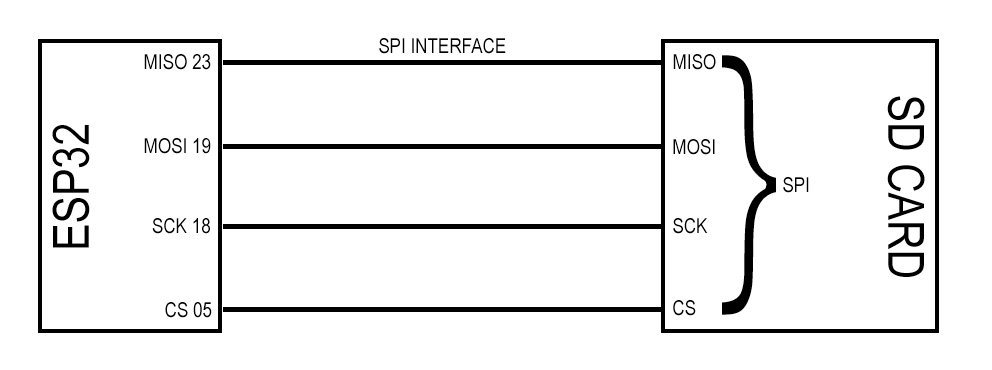
• This program reads analog data from four ADC channels using the Cloud_PLC library and writes the data to a CSV file on an SD card.
• In the setup function, it initializes serial communication, creates a CSV file with column headers, and configures the ADC.
• The loop function reads analog values, converts them to voltage (0-10V range), prints the voltages to the Serial Monitor, and appends the
data to the CSV file every 2 seconds.
Wiring Diagram
Code
#include "Cloud_PLC.h"

File myFile;

void setup()
{
    Serial.begin(115200);

    // Initialize the SD card
    if (!SD.begin())
    {
        Serial.println("SD card initialization failed!");
        return;
    }

    myFile = SD.open("/analog_data.csv", FILE_WRITE);
    if (myFile)
    {
        myFile.println("Analog1,Analog2,Analog3,Analog4");
        myFile.close();
    }
    else
    {
        Serial.println("Error opening analog_data.csv");
    }

    // Configure the ADC
    Cloud_PLC_config_readADC();
}

void loop()
{
    // Read voltages before SD operations
    float voltage0 = Cloud_PLC_getVoltage(0);
    float voltage1 = Cloud_PLC_getVoltage(1);
    float voltage2 = Cloud_PLC_getVoltage(2);
    float voltage3 = Cloud_PLC_getVoltage(3);

    // Print voltages
    Serial.print("\tAnalog1: "); Serial.print(voltage0, 2); Serial.print(" V\t");
    Serial.print("\tAnalog2: "); Serial.print(voltage1, 2); Serial.print(" V\t");
    Serial.print("\tAnalog3: "); Serial.print(voltage3, 2); Serial.print(" V\t");
    Serial.print("\tAnalog4: "); Serial.print(voltage2, 2); Serial.print(" V\t");
    Serial.println();

    // Store voltages to SD card after reading
    myFile = SD.open("/analog_data.csv", FILE_APPEND);
    if (myFile)
    {
        myFile.print(voltage0, 2); myFile.print(", ");
        myFile.print(voltage1, 2); myFile.print(", ");
        myFile.print(voltage2, 2); myFile.print(", ");
        myFile.print(voltage3, 2);
        myFile.println();
        myFile.close();
    }
    else
    {
        Serial.println("Error opening analog_data.csv");
    }

    delay(1000);  // Adjust delay as needed
}
Note
![]() Libraries, User Manuals and Installation guides look into the download section.
Libraries, User Manuals and Installation guides look into the download section.
![]() Install the Cloud PLC libraries(cloudplc.h) before getting start with coding. Download
Install the Cloud PLC libraries(cloudplc.h) before getting start with coding. Download
![]() Above download link, you will find all the IO functionalities included in the Cloud PLC library.
Above download link, you will find all the IO functionalities included in the Cloud PLC library.
![]() In the Arduino IDE, go to the Boards Manager, select the ESP32 board, ensure that you have selected the board version is 1.0.4 and select the com port of the device.
In the Arduino IDE, go to the Boards Manager, select the ESP32 board, ensure that you have selected the board version is 1.0.4 and select the com port of the device.
Real Time Stamp Data (RTC)
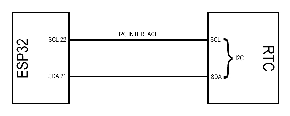
• This program uses the CloudPLCRTC and Cloud_PLC libraries to log real-time data to an SD card.
• In the setup function, it initializes serial communication, creates a CSV file with a header, and sets up the RTC module.
• The loop function retrieves the current date and time from the RTC, prints it to the Serial Monitor, and appends the timestamp to the CSV file
every 3 seconds.
Wiring Diagram
Code
#include "CloudPLCRTC.h"
#include "Cloud_PLC.h"

File myFile;
CloudPLCRTC rtc;

void setup()
{
  Serial.begin(9600);
  delay(1000);

  Cloud_PLC_File_Init();
  myFile = SD.open("/real_time_data.csv", FILE_WRITE);
  if (myFile)
{
    myFile.println("     Real Time DATA     ");
    myFile.close();
  } else
 {
    Serial.println("error opening analog_data.csv");
  }

  rtc.begin();
  // Uncomment the line below to set the RTC to the time this sketch was compiled
  //rtc.adjustToCompileTime();
  // Uncomment the line below to set the RTC to a specific date & time
  //rtc.adjustToDateTime(2024, 7, 8, 17, 41, 10);
}

void loop()
 {
  String formattedDateTime = rtc.getFormattedDateTime();
  Serial.println(formattedDateTime);
  myFile = SD.open("/real_time_data.csv", FILE_APPEND);
  if (myFile)
 {
    myFile.print(formattedDateTime);
    delay(1000);
    myFile.println();
    myFile.close();
  } else
 {
    Serial.println("error opening real_time_data.csv");
  }
  Serial.println();
  delay(3000);
}
Note
![]() Libraries, User Manuals and Installation guides look into the download section.
Libraries, User Manuals and Installation guides look into the download section.
![]() Install the Cloud PLC libraries(cloudplc.h) before getting start with coding. Download
Install the Cloud PLC libraries(cloudplc.h) before getting start with coding. Download
![]() Above download link, you will find all the IO functionalities included in the Cloud PLC library.
Above download link, you will find all the IO functionalities included in the Cloud PLC library.
![]() In the Arduino IDE, go to the Boards Manager, select the ESP32 board, ensure that you have selected the board version is 1.0.4 and select the com port of the device.
In the Arduino IDE, go to the Boards Manager, select the ESP32 board, ensure that you have selected the board version is 1.0.4 and select the com port of the device.
Video
Digital Input WiFi Interface - JSON
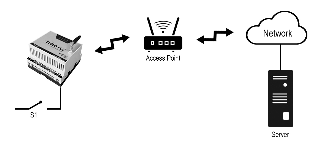
• This program uses the Cloud_PLC library to connect to a WiFi network and send JSON data.
• In the setup function, it initializes serial communication, configures the WiFi connection, and sends an initial JSON payload.
• The loop function continuously checks the state of a digital input (IN1), prints its state to the Serial Monitor, and sends updated JSON data to
a specified URL every 2 seconds.
Wiring Diagram
Code
#include "Cloud_PLC.h"  // Include the header file for Cloud_PLC library

void setup()
{
  Serial.begin(115200);
 // Initialize serial communication at 115200 baud rate
  Cloud_PLC_initialisation();

  Cloud_PLC_Config_WIFI("your SSID", "your password");
  Serial.println("Connecting to WiFi...");            // Call the initialization function for Cloud_PLC
  Serial.println("Sending initial JSON data...");

  Cloud_PLC_JSON("URL", "state", "Initial State");

  Serial.println("Initial JSON data sent!");
}

void loop()
{
  // Check the digital input state of DI1
  const char* inputState;
  if (Cloud_PLC_Digital_Read(DI1) == HIGH)
  {
    inputState = "HIGH";
  } else
  {
    inputState = "LOW";
  }

  // Print the digital input state to the Serial Monitor
  Serial.println(inputState);

  // Send the JSON data
  Cloud_PLC_JSON("https://yourURL.com/CloudplcTest.php", "DIN", inputState);

  delay(2000);  // Wait for 2000 milliseconds (2 seconds)
}
Note
![]() Libraries, User Manuals and Installation guides look into the download section.
Libraries, User Manuals and Installation guides look into the download section.
![]() Install the Cloud PLC libraries(cloudplc.h) before getting start with coding. Download
Install the Cloud PLC libraries(cloudplc.h) before getting start with coding. Download
![]() Above download link, you will find all the IO functionalities included in the Cloud PLC library.
Above download link, you will find all the IO functionalities included in the Cloud PLC library.
![]() In the Arduino IDE, go to the Boards Manager, select the ESP32 board, ensure that you have selected the board version is 1.0.4 and select the com port of the device.
In the Arduino IDE, go to the Boards Manager, select the ESP32 board, ensure that you have selected the board version is 1.0.4 and select the com port of the device.
Video
Digital Input WiFi Interface - MQTT
• This program uses the Cloud_PLC library to connect to WiFi and configure MQTT communication.
• In the setup function, it initializes serial communication, sets up WiFi, and configures MQTT with provided credentials.
• The loop function checks the state of a digital input (IN1), prints the state to the Serial Monitor, and publishes the state to an MQTT topic
every 2 seconds.
Wiring Diagram

Code
#include "Cloud_PLC.h"          // Include the header file for Cloud_PLC library

void setup()
{
  Serial.begin(115200);
  delay(500);
  // Initialize serial communication at 115200 baud rate
  Cloud_PLC_initialisation();

  Serial.println("Configuring to WiFi..."); // Call the initialization function for Cloud_PLC
  Cloud_PLC_Config_WIFI("your SSID", "your password");

  Serial.println("Configuring MQTT...");
  Cloud_PLC_Config_MQTT("yourMQTT_brocker_address", PORT, "username", "password");
  delay(1000);

}

void loop()
{
  // Check the digital input state of DI1
  const char* inputState;
  if (Cloud_PLC_Digital_Read(DI1) == HIGH)
  {
    inputState = "HIGH";
  } else
  {
    inputState = "LOW";
  }

  // Print the digital input state to the Serial Monitor
  Serial.println(inputState);
  Cloud_PLC_MQTT_Publish("DIN", inputState);

  delay(2000); // Wait for 2000 milliseconds (2 seconds)
}
Note
![]() Libraries, User Manuals and Installation guides look into the download section.
Libraries, User Manuals and Installation guides look into the download section.
![]() Install the Cloud PLC libraries(cloudplc.h) before getting start with coding. Download
Install the Cloud PLC libraries(cloudplc.h) before getting start with coding. Download
![]() Above download link, you will find all the IO functionalities included in the Cloud PLC library.
Above download link, you will find all the IO functionalities included in the Cloud PLC library.
![]() In the Arduino IDE, go to the Boards Manager, select the ESP32 board, ensure that you have selected the board version is 1.0.4 and select the com port of the device.
In the Arduino IDE, go to the Boards Manager, select the ESP32 board, ensure that you have selected the board version is 1.0.4 and select the com port of the device.
Video
Controlling Relay By MQTT
• This program connects an Cloud PLC to a Wi-Fi network and an MQTT broker, allowing it to receive commands to control two relays via
MQTT messages.
• The relays are connected to pins 15 and 13 and can be turned on or off by publishing specific messages ("1N" or "1F" for Relay 1, "2N" or
"2F" for Relay 2) to the subscribed topic "CPLRelay."
• The ESP32 maintains the connection to the MQTT broker and handles incoming messages to control the relays accordingly.
Wiring Diagram


Code
	#include <WiFi.h>
#include <PubSubClient.h>

// Replace these with your network credentials and MQTT details
const char* ssid = "your ssid";
const char* password = "your password";
const char* mqtt_server = "MQTT brocker address";
const int mqtt_port = your PORT number;
const char* mqtt_user = "your MQTT username";
const char* mqtt_password = "your password";
const char* subscribe_topic = "CPLRelay";

WiFiClient espClient;
PubSubClient client(espClient);

// Function to connect to WiFi
void setup_wifi() {
  Serial.print("Connecting to ");
  Serial.println(ssid);
  WiFi.begin(ssid, password);

  while (WiFi.status() != WL_CONNECTED)
 {
    delay(500);
    Serial.print(".");
  }

  Serial.println("\nWiFi connected. IP address: ");
  Serial.println(WiFi.localIP());
}

// Callback function for when a message is received
void callback(char* topic, byte* message, unsigned int length)
{
  Serial.print("Message arrived on topic: ");
  Serial.print(topic);
  Serial.print(". Message: ");

  String messageString;
  for (int i = 0; i < length; i++)
 {
    messageString += (char)message[i];
  }
  Serial.println(messageString);

  // Control relays based on the message
  if (messageString.equals("1N"))
{
    digitalWrite(15, HIGH);
  } else if (messageString.equals("1F")) {
    digitalWrite(15, LOW);
  } else if (messageString.equals("2N")) {
    digitalWrite(13, HIGH);
  } else if (messageString.equals("2F")) {
    digitalWrite(13, LOW);
  }
}

// Function to reconnect to MQTT broker
void reconnect()
 {
  while (!client.connected())
{
    Serial.print("Attempting MQTT connection...");
    if (client.connect("ESP32Client", mqtt_user, mqtt_password))
 {
      Serial.println("connected");
      client.subscribe(subscribe_topic);
    } else {
      Serial.print("failed, rc=");
      Serial.print(client.state());
      Serial.println(" try again in 5 seconds");
      delay(5000);
    }
  }
}

void setup()
 {
  Serial.begin(115200);
  pinMode(15, OUTPUT);
  pinMode(13, OUTPUT);
  digitalWrite(15, LOW);
  digitalWrite(13, LOW);

  setup_wifi();
  client.setServer(mqtt_server, mqtt_port);
  client.setCallback(callback);
}

void loop()
 {
  if (!client.connected())
 {
    reconnect();
  }
  client.loop();
}
Note
![]() Libraries, User Manuals and Installation guides look into the download section.
Libraries, User Manuals and Installation guides look into the download section.
![]() Install the Cloud PLC libraries(cloudplc.h) before getting start with coding. Download
Install the Cloud PLC libraries(cloudplc.h) before getting start with coding. Download
![]() Above download link, you will find all the IO functionalities included in the Cloud PLC library.
Above download link, you will find all the IO functionalities included in the Cloud PLC library.
![]() In the Arduino IDE, go to the Boards Manager, select the ESP32 board, ensure that you have selected the board version is 1.0.4 and select the com port of the device.
In the Arduino IDE, go to the Boards Manager, select the ESP32 board, ensure that you have selected the board version is 1.0.4 and select the com port of the device.
Controlling Relay Using WiFi AP
• This code configures the Cloud PLC as a Wi-Fi access point and sets up a web server listening on port 80.
• When a client connects and sends an HTTP request, the server reads the request and checks if it contains "ON" or "OFF" to control a relay
through the Cloud_PLC_Relay_state function.
• The server responds with the relay's status and closes the connection after handling the request
• The access point's IP address is printed to the serial monitor for client connection.
Wiring Diagram


Code
#include "Cloud_PLC.h"
#include <WiFi.h>

  const char* apSSID = "your ssid";       //your SSID
const char* apPassword = "your password"; //Your PASSWORD
WiFiServer server(80);

  void setup()
 {
  Serial.begin(115200);
  setupAccessPoint();        // Set up ESP32 as an access point Cloud_PLC_initialisation();
                            // Initialize the Cloud PLC library
  server.begin();            // Start the server
  Serial.println("Server started");
}

void loop()
{
  WiFiClient client = server.available();  // Check if a client has connected
  if (client)
{
  while (client.connected() && !client.available())
{  // Wait for data from the client
      delay(1);
}

    String request = client.readStringUntil('\r');  // Read the first line of the request
    Serial.println(request);


 if (request.indexOf("ON") != -1)
 {  // Process the request
      Cloud_PLC_Relay_state(0, HIGH);   // Turn on Relay
      client.println("Relay turned ON");
    } else if (request.indexOf("OFF") != -1)
 {
      Cloud_PLC_Relay_state(0, LOW);  // Turn off Relay
      client.println("Relay turned OFF");
    } else
{
      client.println("Invalid command");
    }

    // Close the connection
    client.stop();
  }
}
void setupAccessPoint()
{
  WiFi.softAP(apSSID, apPassword);  // Set up the ESP32 as an access point
  delay(100);
  Serial.println("Access Point IP Address: " + WiFi.softAPIP().toString());
}
Note
![]() Libraries, User Manuals and Installation guides look into the download section.
Libraries, User Manuals and Installation guides look into the download section.
![]() Install the Cloud PLC libraries(cloudplc.h) before getting start with coding. Download
Install the Cloud PLC libraries(cloudplc.h) before getting start with coding. Download
![]() Above download link, you will find all the IO functionalities included in the Cloud PLC library.
Above download link, you will find all the IO functionalities included in the Cloud PLC library.
![]() In the Arduino IDE, go to the Boards Manager, select the ESP32 board, ensure that you have selected the board version is 1.0.4 and select the com port of the device.
In the Arduino IDE, go to the Boards Manager, select the ESP32 board, ensure that you have selected the board version is 1.0.4 and select the com port of the device.
Digital Input Interface - Bluetooth
• This program uses the Cloud_PLC library and Bluetooth Serial to monitor a digital input (IN1) and communicate its state.
• In the setup function, it initializes serial communication for both the Serial Monitor and Bluetooth, allowing pairing with the Bluetooth device
named "Cloud_PLC."
• The loop function checks if IN1 is HIGH or LOW, prints the state to both the Serial Monitor and a paired Bluetooth device, and updates every
500 milliseconds.
Code
#include "Cloud_PLC.h"
#include "BluetoothSerial.h"
//Include the header file for Cloud_PLC library
BluetoothSerial SerialBT;

void setup()
{
  Serial.begin(115200);
  SerialBT.begin("Cloud_PLC");
  Serial.print("The device started, Now you can pair it with bluetooth");
  //Initialize serial communication at 115200 baud rate
  Cloud_PLC_initialisation();
  //Call the initialization function for Cloud_PLC
}

void loop()

{
  // Check the digital input state of DI1

  if (Cloud_PLC_Digital_Read(DI1) == HIGH)  //input channel, IN1,IN2,IN3,IN4,IN4
  {
    Serial.println("HIGH");
    SerialBT.println("HIGH");
    // Print "ON" to the Serial Monitor if IN1 is HIGH
    delay(500);

  }
  else
  {
    Serial.println("LOW");
    SerialBT.println("LOW");    // Print "OFF" to the Serial Monitor if IN1 is not
    delay(500);
    // Wait for 2000 milliseconds (2 seconds)

  }
}
Note
![]() Libraries, User Manuals and Installation guides look into the download section.
Libraries, User Manuals and Installation guides look into the download section.
![]() Install the Cloud PLC libraries(cloudplc.h) before getting start with coding. Download
Install the Cloud PLC libraries(cloudplc.h) before getting start with coding. Download
![]() Above download link, you will find all the IO functionalities included in the Cloud PLC library.
Above download link, you will find all the IO functionalities included in the Cloud PLC library.
![]() In the Arduino IDE, go to the Boards Manager, select the ESP32 board, ensure that you have selected the board version is 1.0.4 and select the com port of the device.
In the Arduino IDE, go to the Boards Manager, select the ESP32 board, ensure that you have selected the board version is 1.0.4 and select the com port of the device.
Controlling Relay By Bluetooth
• This code sets up an Cloud PLC to control two relays via Bluetooth.
• It initializes the relays as outputs and starts Bluetooth communication with a device name "CPL_Relays."
• In the loop function, it listens for incoming Bluetooth commands to control the relays: "ON1" and "OFF1" for Relay 1, and "ON2" and
"OFF2" for Relay 2. It also provides feedback over Bluetooth and prints received commands for debugging.
Code
#include <BluetoothSerial.h>

  // Define the relay pins
  #define RELAY1_PIN 15
  #define RELAY2_PIN 13

  // Create a BluetoothSerial object
  BluetoothSerial SerialBT;

  void setup()
  {
    // Initialize serial communication for debugging
    Serial.begin(115200);

    // Initialize the relay pins as outputs
    pinMode(RELAY1_PIN, OUTPUT);
    pinMode(RELAY2_PIN, OUTPUT);

    // Set the relays to be off initially
    digitalWrite(RELAY1_PIN, LOW);
    digitalWrite(RELAY2_PIN, LOW);

    // Begin serial communication over Bluetooth
    SerialBT.begin("CPL_Relays"); // Bluetooth device name
    Serial.println("Bluetooth device started, you can now pair it with Bluetooth!");
  }

  void loop()
     {
    // Check if data is available on the Bluetooth serial
    if (SerialBT.available())
     {
      // Read the incoming string
      String request = SerialBT.readStringUntil('\n');


 // Print the received string to the Serial Monitor (for debugging)


      Serial.print("Received: ");
      Serial.println(request);

      // Control the relays based on the received command
      if (request.indexOf("ON1") != -1)
      {
        digitalWrite(RELAY1_PIN, HIGH); // Turn Relay 1 on
        SerialBT.println("Relay 1 turned ON");
      }
      else if (request.indexOf("OFF1") != -1)
      {
        digitalWrite(RELAY1_PIN, LOW); // Turn Relay 1 off
        SerialBT.println("Relay 1 turned OFF");
      }
      else if (request.indexOf("ON2") != -1)
      {
        digitalWrite(RELAY2_PIN, HIGH); // Turn Relay 2 on


      SerialBT.println("Relay 2 turned ON");
      }
      else if (request.indexOf("OFF2") != -1)
      {
        digitalWrite(RELAY2_PIN, LOW); // Turn Relay 2 off
        SerialBT.println("Relay 2 turned OFF");
      }
      else
      {
        SerialBT.println("Invalid command");
      }
    }
  }
Note
![]() Libraries, User Manuals and Installation guides look into the download section.
Libraries, User Manuals and Installation guides look into the download section.
![]() Install the Cloud PLC libraries(cloudplc.h) before getting start with coding. Download
Install the Cloud PLC libraries(cloudplc.h) before getting start with coding. Download
![]() Above download link, you will find all the IO functionalities included in the Cloud PLC library.
Above download link, you will find all the IO functionalities included in the Cloud PLC library.
![]() In the Arduino IDE, go to the Boards Manager, select the ESP32 board, ensure that you have selected the board version is 1.0.4 and select the com port of the device.
In the Arduino IDE, go to the Boards Manager, select the ESP32 board, ensure that you have selected the board version is 1.0.4 and select the com port of the device.
Embedded Webserver
• This program sets up a web server using a Cloud PLC to control two relays through a web interface.
• In the setup function, it initializes serial communication, connects to Wi-Fi, and starts the web server.
• The loop function listens for incoming HTTP requests, parses them to control the relays based on the URL path, and serves a simple HTML
page to control the relays.
• It updates the relay states and serves the appropriate HTML based on user interactions with the web page.
Wiring Diagram
Code
#include <Cloud_PLC.h>

WiFiServer server(80);  // Set web server port number to 80
String header;          // Variable to store the HTTP request
const int relayPin1 = 15;  // Relay pins
const int relayPin2 = 13;  // Relay pins
String relayState1 = "OFF";    // Current state of the relays
String relayState2 = "OFF";

void setup()
{
  Serial.begin(115200);
  pinMode(relayPin1, OUTPUT); // Initialize the relay pins as outputs
  pinMode(relayPin2, OUTPUT);
  digitalWrite(relayPin1, LOW);
  digitalWrite(relayPin2, LOW);

  Cloud_PLC_Config_WIFI("TEST", "12345678");  // Connect to Wi-Fi network
  server.begin();  // Start the server
}
void loop()
{
  WiFiClient client = server.available();   // Listen for incoming clients
  if (client)
  { // If a new client connects,
    Serial.println("New Client.");          // Print a message out in the serial port
    String currentLine = "";                // Make a String to hold incoming data from the client
    while (client.connected())
    { // Loop while the client's connected
      if (client.available())

 { // If there's bytes to read from the client,
        char c = client.read();             // Read a byte, then
        Serial.write(c);                    // Print it out the serial monitor
        header += c;
        if (c == '\n')
        { // If the byte is a newline character
          if (currentLine.length() == 0)


{ // If the current line is blank, you got two newline characters in a row.
            // That's the end of the client HTTP request, so send a response:
            client.println("HTTP/1.1 200 OK");
            client.println("Content-type:text/html");
            client.println("Connection: close");
            client.println();
            // Display the HTML web page
            client.println("<!DOCTYPE html><html>");
            client.println("<head><meta name=\"viewport\" content=\"width=device-width, initial-scale=1\">");
            client.println("<link rel=\"icon\" href=\"data:,\">");
            client.println("<style>body { text-align: center; font-family: Arial; } .button { background-color: #4CAF50; border: none; color: white; padding: 15px 32px; text-align: center; text-decoration: none; display: inline-block; font-size: 16px; margin: 4px 2px; cursor: pointer; } .button2 {background-color: #ff0000;}</style></head>");
            client.println("<body><h1>Cloud PLC Relay Control</h1>");

            client.println("<p>Relay 1 - State " + relayState1 + "</p>");
            if (relayState1 == "OFF")
            {
              client.println("<p><a href=\"/relay1/on\"><button class=\"button\">ON</button></a></p>");
            } else
            {
              client.println("<p><a href=\"/relay1/off\"><button class=\"button button2\">OFF</button></a></p>");
            }
            client.println("<p>Relay 2 - State " + relayState2 + "</p>");
            if (relayState2 == "OFF")
            {
              client.println("<p><a href=\"/relay2/on\"><button class=\"button\">ON</button></a></p>");
            } else
            {
              client.println("<p><a href=\"/relay2/off\"><button class=\"button button2\">OFF</button></a></p>");
            }
            client.println("</body></html>");
            client.println();   // The HTTP response ends with another blank line
            break;  // Break out of the while loop
          }


 else
          { // If you got a newline, then clear currentLine
            currentLine = "";
          }
        }
          else if (c != '\r')
        { // If you got anything else but a carriage return character,
          currentLine += c;      // Add it to the end of the currentLine
        }
        // Check if the client request is to turn relay 1 on or off
        if (header.indexOf("GET /relay1/on") >= 0)
        {
          relayState1 = "ON";
          digitalWrite(relayPin1, HIGH);
        } else if (header.indexOf("GET /relay1/off") >= 0)
        {
          relayState1 = "OFF";
          digitalWrite(relayPin1, LOW);
        }
        // Check if the client request is to turn relay 2 on or off
        if (header.indexOf("GET /relay2/on") >= 0)
        {
          relayState2 = "ON";
          digitalWrite(relayPin2, HIGH);
        } else if (header.indexOf("GET /relay2/off") >= 0)
        {
          relayState2 = "OFF";
          digitalWrite(relayPin2, LOW);
        }
      }
    }
    // Clear the header variable
    header = "";
    client.stop();  // Close the connection
    Serial.println("Client disconnected.");
    Serial.println("");
  }
}
Note
![]() Libraries, User Manuals and Installation guides look into the download section.
Libraries, User Manuals and Installation guides look into the download section.
![]() Install the Cloud PLC libraries(cloudplc.h) before getting start with coding. Download
Install the Cloud PLC libraries(cloudplc.h) before getting start with coding. Download
![]() Above download link, you will find all the IO functionalities included in the Cloud PLC library.
Above download link, you will find all the IO functionalities included in the Cloud PLC library.
![]() In the Arduino IDE, go to the Boards Manager, select the ESP32 board, ensure that you have selected the board version is 1.0.4 and select the com port of the device.
In the Arduino IDE, go to the Boards Manager, select the ESP32 board, ensure that you have selected the board version is 1.0.4 and select the com port of the device.
Video
LoRa Sender
• This program establishes an Ethernet connection using an ESP32 and Ethernet shield, allowing the device to communicate with a server at a specified IP address and port.
• It attempts to connect to the server and, if successful, sends a greeting message ("Hello, server!").
• The program continuously checks for incoming data from the server, prints it to the Serial Monitor, and allows the user to send data back to the server via the serial input. If the connection to the server is lost, it retries the connection.
This code initializes a LoRa (Long Range) communication module to send a "Hello, receiver!" message every 2 seconds over the 433 MHz frequency. It configures the LoRa module with specific pin connections and checks if initialization is successful. If successful, it repeatedly transmits the message and prints "Message Sent" to the serial monitor.
#include <SPI.h>
#include <LoRa.h>
#define NSS_PIN 5
#define RESET_PIN 13
#define DIO0_PIN 2
void setup()
{
Serial.begin(9600);
while (!Serial);
LoRa.setPins(NSS_PIN, RESET_PIN, DIO0_PIN);
if (!LoRa.begin(433E6))
{
 Serial.println("LoRa initialization failed. Check your connections.");
 while (1);
}
Serial.println("LoRa Initialized");
}
void loop()
{
String message = "Hello, receiver!";
LoRa.beginPacket();
LoRa.print(message);
LoRa.endPacket();
Serial.println("Message Sent");
delay(2000); // Adjust as needed
}
Note
![]() Libraries, User Manuals and Installation guides look into the download section.
Libraries, User Manuals and Installation guides look into the download section.
![]() Install the Cloud PLC libraries(cloudplc.h) before getting start with coding. Download
Install the Cloud PLC libraries(cloudplc.h) before getting start with coding. Download
![]() Above download link, you will find all the IO functionalities included in the Cloud PLC library.
Above download link, you will find all the IO functionalities included in the Cloud PLC library.
![]() In the Arduino IDE, go to the Boards Manager, select the ESP32 board, ensure that you have selected the board version is 1.0.4 and select the com port of the device.
In the Arduino IDE, go to the Boards Manager, select the ESP32 board, ensure that you have selected the board version is 1.0.4 and select the com port of the device.
LoRa Receiver
• This code sets up an Arduino with an Ethernet shield as a Modbus TCP server.
• It initializes the Ethernet connection with a specified MAC and IP address and configures the Modbus server to handle requests.
• Four holding registers (10, 11, 12, and 13) are defined and initialized with specific values.
• The server continuously processes Modbus TCP queries in the loop() function.
This code initializes a LoRa module for receiving messages over the 433 MHz frequency. It sets up the LoRa module using specified pins and checks if initialization is successful. In the `loop()` function, it continuously listens for incoming packets. When a packet is received, it reads and prints the message to the serial monitor.
#include <SPI.h>
#include <LoRa.h>
#define NSS_PIN 5 // Choose any GPIO pin for NSS
#define RESET_PIN 13 // Choose any GPIO pin for RESET
#define DIO0_PIN 2 // Choose any GPIO pin for DIO0
void setup()
{
Serial.begin(9600);
while (!Serial);
LoRa.setPins(NSS_PIN, RESET_PIN, DIO0_PIN);
if (!LoRa.begin(433E6))
{
 Serial.println("LoRa initialization failed. Check your connections.");
 while (1);
}
Serial.println("LoRa Initialized");
}
void loop()
{
if (LoRa.parsePacket())
{
 // Received a packet
 while (LoRa.available())
{
 Serial.print((char)LoRa.read());
 }
 Serial.println();
}
}
Note
![]() Libraries, User Manuals and Installation guides look into the download section.
Libraries, User Manuals and Installation guides look into the download section.
![]() Install the Cloud PLC libraries(cloudplc.h) before getting start with coding. Download
Install the Cloud PLC libraries(cloudplc.h) before getting start with coding. Download
![]() Above download link, you will find all the IO functionalities included in the Cloud PLC library.
Above download link, you will find all the IO functionalities included in the Cloud PLC library.
![]() In the Arduino IDE, go to the Boards Manager, select the ESP32 board, ensure that you have selected the board version is 1.0.4 and select the com port of the device.
In the Arduino IDE, go to the Boards Manager, select the ESP32 board, ensure that you have selected the board version is 1.0.4 and select the com port of the device.
Cloud PLC Programming Using Ladder Logic


