
Search results for 'tắt nguồn xiaomi redmi note 13r không cần nút nguồn'
-
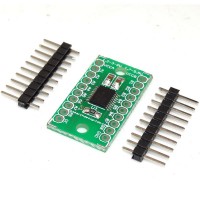
Because the Arduino (and Basic Stamp) are 5V devices, and most modern sensors, displays, flash cards and modes are 3.3V-only, many makers find that they need to perform level shifting/conversion to protect the 3.3V device from 5V.This 8-bit noninverting translator uses two separate configurable power-supply rails. The A port is designed to track VCCA. VCCA accepts any supply voltage from 1.2 V to 3.6 V. The B port is designed to track VCCB. VCCB accepts any supply voltage from 1.65 V to 5.5 V. This allows for universal low-voltage bidirectional translation between any of the 1.2-V, 1.5-V, 1.8-V, 2.5-V, 3.3-V, and 5-V voltage nodes. VCCA should not exceed VCCB.
Order Code : RDL/8BLC/14/001/V1.0
Learn More -
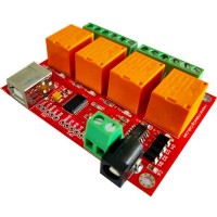
This relay board with 4 SPDT relays and digital IO controlled via USB protocol, Suitable for home automation applications, hobby projects, and industrial automation. The free software application allows controlling relays manually or automatic operation by creating timers for each channel and enabling repeat cycle. Relay module support Windows & Linux platform, .Net / JAVA / Python SDK available for developing custom application.
Order Code: RDL/4RB/14/001/V4.0
Learn More -
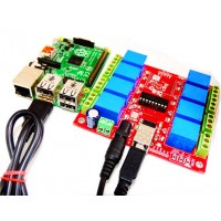
USB 8 Channel Relay Board FT245RL is controlled by computer USB port. The USB Relay Board is with 8 SPDT relays rated up to 7A each. You may control devices 230V / 120V (up to 8) directly with one such relay unit. Suitable for home automation applications, hobby projects, industrial automation.
Order Code : RDL/8RB/14/001/V2.0
Learn More -
The Internet of Things (IoT) is the interconnection of uniquely identifiable embedded computing devices within the existing Internet infrastructure.
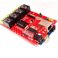
Web shield is a smart communication shield for controlling and monitoring embedded application via internet.Internet is the media and economic way for communication between anywhere from to geographical location.This shield is compatible with Arduino open source and make easy way for customized application development.This shield has got four relay 10AMP.The board by ULN2003 IC. The board works on 5V.
Order Code : RDL/ERS/14/001/V1.0
Learn More -
One of the basic interfacing requirements for the hobbyists or electronics enthusiasts is I/P (keypad) and O/P (LCD display) for proyotype applications. This shield uses minimum number I/O’s that is 2 bits(D0 and D1) for LCD data . 5 input key switches (Navigation keys), when it's activated serial data will be sent to pin D0 by internal 2 line LCD controller. Each key has been pulled up to a different voltage level, so a different voltage will be generated every time a user selects a key. This voltage could be read by the analog pin of internal 2 line LCD controller on the board. Hence saves the no of I/O pins. The backlight of the LCD could be controlled by setting PWM (Pin D10) by adding a few lines of code.
Order Code : RDL/LKS/14/001/V1.0
Learn More -
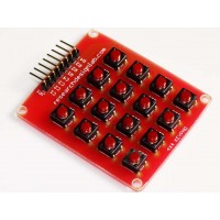
A 4x4 matrix keypad requiring eight Input/Output ports for interfacing isused as an example. Rows are connected to Peripheral Input/Output (PIO) pins configured as output. Columns are connected to PIO pins configured as input with interrupts. In this configuration, four pull-up resistors must be added in order to apply a high level on the corresponding input pins.
Note: The color of the PCB may vary. However the circuit/pinout of the PCB will remain same.
Order Code : RDL/4X4KP/13/001/V2.0
Learn More -
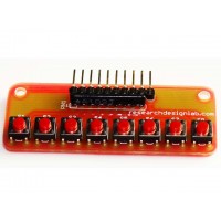
It has 8 keys which can be connected to any microcontroller or any interfacing kit directly. KEY is a small key pad designed to data entries for microcontroller board.The board has 10-pin header for 10-wire ribbon cable. By default the switch status would be pulled up, every time you press a key the corresponding switch header changes its state to the common header in the board.
Note: The color of the PCB may vary. However the circuit/pinout of the PCB will remain same.
Order Code : RDL/8SW/13/001/V1.1
Learn More -
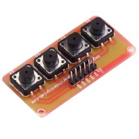
It has 4 keys which can be connected to any microcontroller or any interfacing kit directly. KEY is a small key pad designed to data entries for microcontroller board.The board has 6-pin header for 6-wire ribbon cable. By default the switch status would be pulled up, every time you press a key the corresponding switch header changes its state to the common header in the board.
Order Code : RDL/4SW/13/001/V1.1
Learn More -
2 Keys Keypad can be connected to any microcontroller or any interfacing kit directly. KEY is a small keypad designed to data entries for microcontroller board. The board has 4-pin header for 4-wire ribbon cable. By default the switch status would be pulled up, every time you press a key the corresponding switch header changes its state to the common header in the board.
Order Code : RDL/2SW/14/001/V1.0
Learn More -
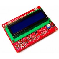
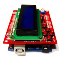
One of the basic interfacing requirements for the hobbyists or electronics enthusiasts is I/P (keypad) and O/P (LCD display) for proyotype applications. This shield uses minimum number I/O’s that is 4 bits for LCD data and 2 control signal lines for the same. A single analog pin (Pin A0) is multiplexed to read 5 input key switches (Navigation keys). Each key has been pulled up to a different voltage level, so a different voltage will be generated every time a user selects a key. This voltage could be read by the analog pin A0 on the board. Hence saves the no of I/O pins. The backlight of the LCD could be controlled by setting PWM (Pin D10) by adding a few lines of code.
Order Code : RDL/RLSS/14/001/V1.0
Learn More