
Search results for 'Remote Power Management and Meter Reading System Based on ARM microprocesor'
-

This Book is all about Interfacing VB.net with Embedded System.This Book is NOT FOR SALE , Only knowledge base for Open Source Community.
Download:
Learn More Interfacing VB.NET with Embedded System
 -
This Book is all about Interfacing Embedded System with Matlab. This book guides the beginners for creating GUI , Modeling with SimuLink & Interfacing Arduino , Raspberry Pi , BeagleBone with Embedded System. This Book is NOT FOR SALE , Only knowledge base for Open Source Community.
Learn More -
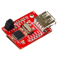
USB Host Board now makes it even easier to integrate USB functionality into your products and with the USB Host device you can implement USB Host Controller functionality in no time at all. The FT311D provides a bridge between peripheral hardware and an Android platform with a USB device port.
ORDER CODE: RDL/HBS/15/001/V1.0
Learn More -
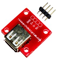
This adapters allow you to quickly and easily mount a USB Type A Female connector onto a breadboard or prototype boards. This breakout board brings all 4 pins of its USB Type A Female socket out to prototyping work.Each pin brought to the male header pins. There are some prototyping area with 0.1" (2.54mm) spacing, allowing easy addition of simple circuits.
Order Code : RDL/UBA/14/001/V1.0
Learn More -
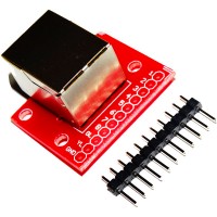
This adapters allow you to quickly and easily mount a RJ45 connector onto a breadboard or prototype boards. This breakout board brings all 8 pins of its RJ45 socket out to prototyping work. Each pin brought to the male header pins. There are some prototyping area with 0.1" (2.54mm) spacing, allowing easy addition of simple circuits.
Order Code : RDL/RJ45/14/001/V1.0
Learn More -
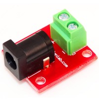
This adapter allows you to connect a 2.5 mm barrel jack connector to bare wires. One end has 3 pin screw terminals . If you have a power supply with a barrel jack and want to plug it into a breadboard, this might be the simple solution.
Order Code : RDL/DSB/14/001/V1.0
Learn More -
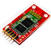
This module enables you to wireless transmit & receive serial data. It is a drop in replacement for wired serial connections allowing transparent two way data communication. You can simply use it for serial port replacement to establish connection between MCU or embedded project and PC for data transfer. This board operates on 5V and has LED indication and 3V regulator.
Order Code : RDL/BL-06/14/001/V1.0
Learn More -
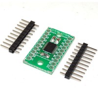
Because the Arduino (and Basic Stamp) are 5V devices, and most modern sensors, displays, flash cards and modes are 3.3V-only, many makers find that they need to perform level shifting/conversion to protect the 3.3V device from 5V.This 8-bit noninverting translator uses two separate configurable power-supply rails. The A port is designed to track VCCA. VCCA accepts any supply voltage from 1.2 V to 3.6 V. The B port is designed to track VCCB. VCCB accepts any supply voltage from 1.65 V to 5.5 V. This allows for universal low-voltage bidirectional translation between any of the 1.2-V, 1.5-V, 1.8-V, 2.5-V, 3.3-V, and 5-V voltage nodes. VCCA should not exceed VCCB.
Order Code : RDL/8BLC/14/001/V1.0
Learn More -
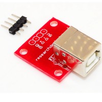
This simple board breaks out a female USB type B connector’s VCC, GND, D- and D+ pins to a 0.1" pitch header. The +5V and GND pins can be used to power your project from USB, while the D- and D+ pins give you access to the USB’s differential data signal.
Order Code : RDL/UBB/14/001/V1.0
Learn More -
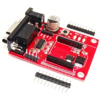
This is a simple to use, RS232 to serial base unit for the XBee line. This unit works with all XBee modules including the Series 1 and Series 2.5, standard and Pro version. Plug the unit into the XBee Development Board, attach a RS232 cable, and you will have direct access to the serial and programming pins on the XBee unit.
Order Code : RDL/XSU/14/001/V1.0
Learn More