
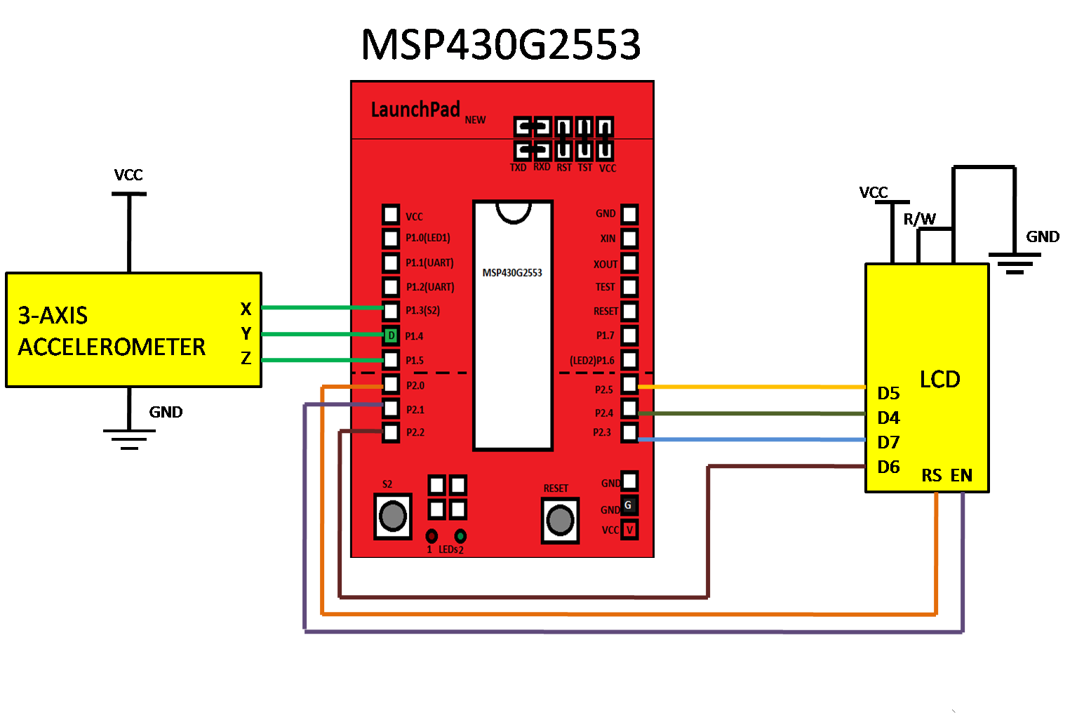
3 axis accelerometer Interfacing with MSP430
// create file named called 3axisaccelerometer.c and paste below given program
/*
* Project name:
3-AXIS ACCELEROMETER
* Copyright
(c) Researchdesignlab.com
* Test configuration:
MCU: MSP430G2553
Dev.Board: TI LAUNCHPAD
Oscillator: 16 MHz
Software: CCS STUDIO V.5
*/
#include "msp430g2553.h"
#include "lcd.h"
#define LED1 BIT0
int itoa(int n, char* out);
void reverse(char* str, int length);
//int temp;
char buffer[33];
char buffer2[33];
char buffer3[33];
int itoa(int n, char* out)
{
// if negative, need 1 char for the sign
int sign = n < 0? 1: 0;
int i = 0;
if (n == 0) {
out[i++] = '0';
} else if (n < 0) {
out[i++] = '-';
n = -n;
}
while (n > 0) {
out[i++] = '0' + n % 10;
n /= 10;
}
out[i] = '\0';
reverse(out + sign, i - sign);
return 0;
}
void reverse(char* str, int length){
int i = 0, j = length-1;
char tmp;
while (i < j) {
tmp = str[i];
str[i] = str[j];
str[j] = tmp;
i++; j--;
}
}
int main(void)
{
WDTCTL = WDTPW + WDTHOLD; //Stop WDT
BCSCTL1 = CALBC1_8MHZ; //Set DCO to 8Mhz
DCOCTL = CALDCO_8MHZ; //Set DCO to 8Mhz
P1DIR &= ~0xF0; // set pin direction for led
P1DIR |= BIT0;
P2DIR&=~BIT3;
InitializeLcm(); //INITIALIZE LCD
__delay_cycles(1000000);
__enable_interrupt();
int value;
char *text;
while(1)
{
ADC10CTL1 = INCH_3 + ADC10DIV_3 ;
ADC10CTL0 = SREF_0 + ADC10SHT_3 + ADC10ON + ADC10IE;
ADC10AE0 |= BIT3;
ADC10CTL0 |= ENC + ADC10SC; // Sampling and conversion start
__bis_SR_register(CPUOFF + GIE); // LPM0 with interrupts enabled
value = ADC10MEM;
itoa(value,buffer);
ClearLcmScreen();
PrintStr("X="); //DISPLAY ON LCD
PrintStr(buffer);
__delay_cycles(100000); // Wait for ADC Ref to settle
ADC10CTL1 = INCH_4 + ADC10DIV_3 ;
ADC10CTL0 = SREF_0 + ADC10SHT_3 + ADC10ON + ADC10IE;
ADC10AE0 |= BIT4;
ADC10CTL0 |= ENC + ADC10SC; // Sampling and conversion start
__bis_SR_register(CPUOFF + GIE); // LPM0 with interrupts enabled
value = ADC10MEM;
itoa(value,buffer2);
ClearLcmScreen();
PrintStr("Y="); //DISPLAY ON LCD
PrintStr(buffer2);
__delay_cycles(100000);
ADC10CTL1 = INCH_5 + ADC10DIV_3 ;
ADC10CTL0 = SREF_0 + ADC10SHT_3 + ADC10ON + ADC10IE;
ADC10AE0 |= BIT5;
ADC10CTL0 |= ENC + ADC10SC; // Sampling and conversion start
__bis_SR_register(CPUOFF + GIE); // LPM0 with interrupts enabled
value = ADC10MEM;
itoa(value,buffer3);
ClearLcmScreen();
PrintStr("Z="); //DISPLAY ON LCD
PrintStr(buffer3);
__delay_cycles(100000);
}
}
// ADC10 interrupt service routine
#pragma vector=ADC10_VECTOR
__interrupt void ADC10_ISR (void)
{
__bic_SR_register_on_exit(CPUOFF); // Return to active mode
P1OUT ^= LED1;
}
// end of 3axisaccelerometer.c file
//…………………………………………………………………………………………..
// create file named called lcd.c and paste below given program
#include "msp430g2553.h"
#include "lcd.h"
#define LCM_DIR P2DIR
#define LCM_OUT P2OUT
// Define symbolic LCM - MCU pin mappings
// We've set DATA PIN TO 4,5,6,7 for easy translation
//
#define LCM_PIN_RS BIT0 // P2.0
#define LCM_PIN_EN BIT1 // P2.1
#define LCM_PIN_D7 BIT3 // P2.3
#define LCM_PIN_D6 BIT2 // P2.2
#define LCM_PIN_D5 BIT5 // P2.5
#define LCM_PIN_D4 BIT4 // P2.4
#define LCM_PIN_MASK ((LCM_PIN_RS | LCM_PIN_EN | LCM_PIN_D7 | LCM_PIN_D6 | LCM_PIN_D5 | LCM_PIN_D4))
#define FALSE 0
#define TRUE 1
//
// Routine Desc:
//
// This is the function that must be called
// whenever the LCM needs to be told to
// scan it's data bus.
//
// Parameters:
//
// void.
//
// Return
//
// void.
//
void PulseLcm()
{
//
// pull EN bit low
//
LCM_OUT &= ~LCM_PIN_EN;
__delay_cycles(200);
//
// pull EN bit high
//
LCM_OUT |= LCM_PIN_EN;
__delay_cycles(200);
//
// pull EN bit low again
//
LCM_OUT &= (~LCM_PIN_EN);
__delay_cycles(200);
}
//
// Routine Desc:
//
// Send a byte on the data bus in the 4 bit mode
// This requires sending the data in two chunks.
// The high nibble first and then the low nible
//
// Parameters:
//
// ByteToSend - the single byte to send
//
// IsData - set to TRUE if the byte is character data
// FALSE if its a command
//
// Return
//
// void.
//
void SendByte(char ByteToSend, int IsData)
{
//
// clear out all pins
//
LCM_OUT &= (~LCM_PIN_MASK);
//
// set High Nibble (HN) -
// usefulness of the identity mapping
// apparent here. We can set the
// DB7 - DB4 just by setting P1.7 - P1.4
// using a simple assignment
//
LCM_OUT |= (ByteToSend & 0xF0);
if (IsData == TRUE)
{
LCM_OUT |= LCM_PIN_RS;
}
else
{
LCM_OUT &= ~LCM_PIN_RS;
}
//
// we've set up the input voltages to the LCM.
// Now tell it to read them.
//
PulseLcm();
//
// set Low Nibble (LN) -
// usefulness of the identity mapping
// apparent here. We can set the
// DB7 - DB4 just by setting P1.7 - P1.4
// using a simple assignment
//
LCM_OUT &= (~LCM_PIN_MASK);
LCM_OUT |= ((ByteToSend & 0x0F) << 4);
if (IsData == TRUE)
{
LCM_OUT |= LCM_PIN_RS;
}
else
{
LCM_OUT &= ~LCM_PIN_RS;
}
//
// we've set up the input voltages to the LCM.
// Now tell it to read them.
//
PulseLcm();
}
//
// Routine Desc:
//
// Set the position of the cursor on the screen
//
// Parameters:
//
// Row - zero based row number
//
// Col - zero based col number
//
// Return
//
// void.
//
void LcmSetCursorPosition(char Row, char Col)
{
char address;
//
// construct address from (Row, Col) pair
//
if (Row == 0)
{
address = 0;
}
else
{
address = 0x40;
}
address |= Col;
SendByte(0x80 | address, FALSE);
}
//
// Routine Desc:
//
// Clear the screen data and return the
// cursor to home position
//
// Parameters:
//
// void.
//
// Return
//
// void.
//
void ClearLcmScreen()
{
//
// Clear display, return home
//
SendByte(0x01, FALSE);
SendByte(0x02, FALSE);
}
//
// Routine Desc:
//
// Initialize the LCM after power-up.
//
// Note: This routine must not be called twice on the
// LCM. This is not so uncommon when the power
// for the MCU and LCM are separate.
//
// Parameters:
//
// void.
//
// Return
//
// void.
//
void InitializeLcm(void)
{
//
// set the MSP pin configurations
// and bring them to low
//
LCM_DIR |= LCM_PIN_MASK;
LCM_OUT &= ~(LCM_PIN_MASK);
//
// wait for the LCM to warm up and reach
// active regions. Remember MSPs can power
// up much faster than the LCM.
//
__delay_cycles(100000);
//
// initialize the LCM module
//
// 1. Set 4-bit input
//
LCM_OUT &= ~LCM_PIN_RS;
LCM_OUT &= ~LCM_PIN_EN;
LCM_OUT = 0x20;
PulseLcm();
//
// set 4-bit input - second time.
// (as reqd by the spec.)
//
SendByte(0x28, FALSE);
//
// 2. Display on, cursor on, blink cursor
//
SendByte(0x0E, FALSE);
//
// 3. Cursor move auto-increment
//
SendByte(0x01, FALSE);
}
//
// Routine Desc
//
// Print a string of characters to the screen
//
// Parameters:
//
// Text - null terminated string of chars
//
// Returns
//
// void.
//
void PrintStr(char *Text)
{
char *c;
c = Text;
while ((c != 0) && (*c != 0))
{
SendByte(*c, TRUE);
c++;
}
}
//
// Routine Desc
//
// main entry point to the sketch
//
// Parameters
//
// void.
//
// Returns
//
// void.
//
// end of lcd.c file
//…………………………………………………………………………………………..
// create file named called lcd.h and paste below given program
void PulseLcm();
void SendByte(char ByteToSend, int IsData);
void LcmSetCursorPosition(char Row, char Col);
void ClearLcmScreen();
void InitializeLcm(void);
void PrintStr(char *text);
// end of lcd.h file
//…………………………………………………………………………………………..